35 moment and shear diagram
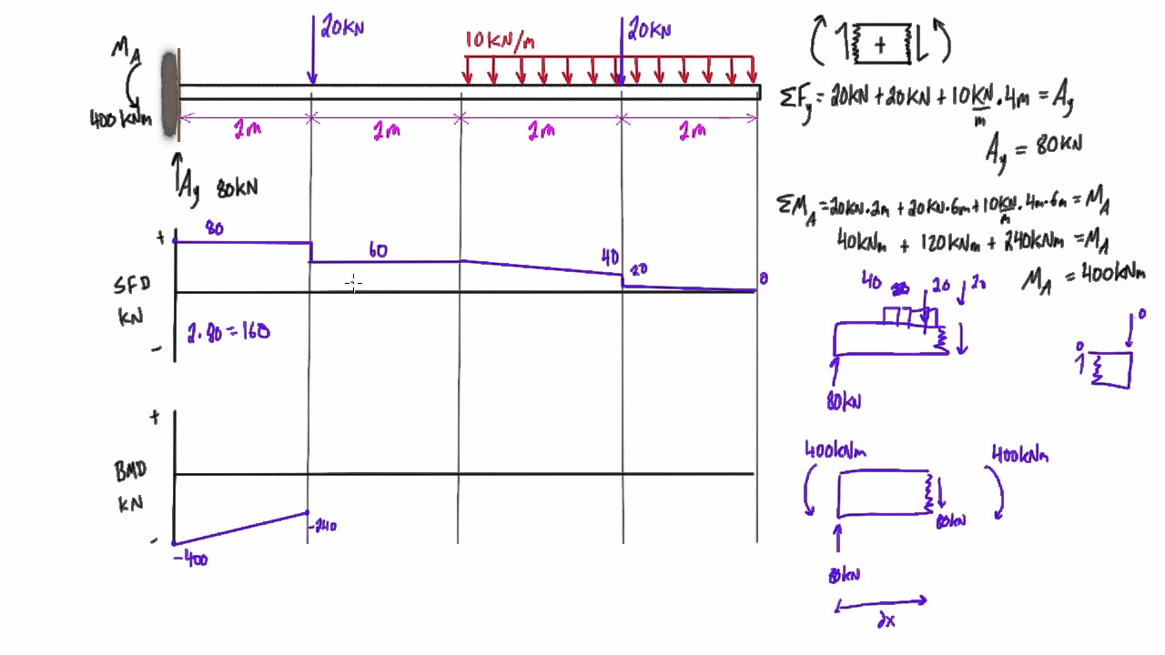
3.2 - Shear Force & Bending Moment Diagrams What if we sectioned the beam and exposed internal forces and moments. This exposes the internal Normal Force Shear Force Bending Moment ! What if we performed many section at ifferent values Of x, we will be able to plot the internal forces and bending moments, N(x), V(x), M(x) as a function Of position! The x-axis will represent the location (lined up with the shear diagram and free body diagram above), and the y-axis will represent the internal bending moment. Starting at zero at the right side of the plot, you will move to the right, pay attention to shear diagram and the moments in the free body diagram above.
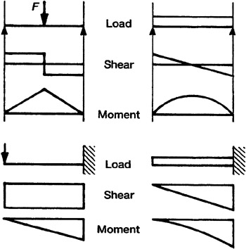
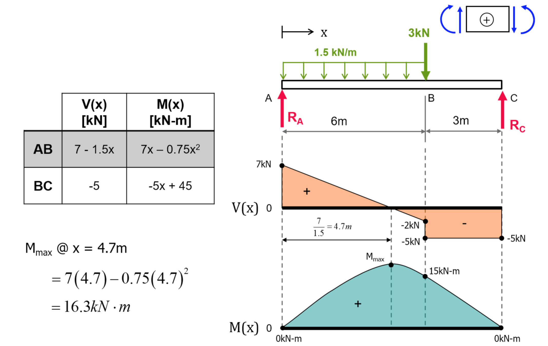
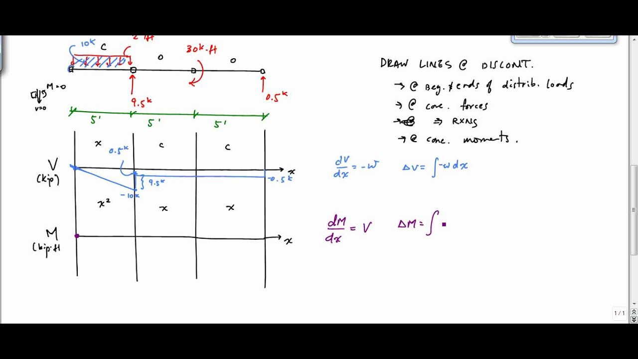
First draw the free-body-diagram of the beam with sufficient room under it for the shear and moment diagrams (if needed, solve for support reactions first). 2. Draw the shear diagram under the free-body-diagram. The distributed load is the slope of the shear diagram and each point load represents a jump in the shear diagram.

Moment and shear diagram
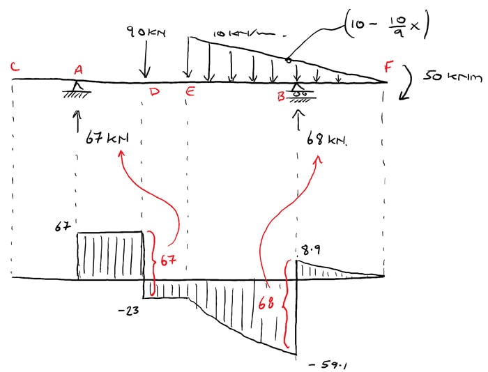
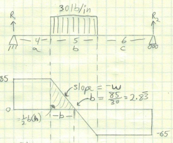
PDF_C8_b (Shear Forces and Bending Moments in Beams) Q6: A simply supported beam with a triangularly distributed downward load is shown in Fig. Calculate reaction; draw shear force diagram; find location of V=0; calculate maximum moment, and draw the moment diagram. 6k/ft 9 ft RA = (27k)(9-6)/9= 9k A B F = (0.5x6x9) = 27k x = (2/3)(9) = 6 ft Shear Diagram: Moment Diagram: 1. Point loads cause a vertical jump in the shear diagram. The direction of the jump is the same as the sign of the point load. 2. Udl result in a straight, sloped line on the shear diagram. 3. The shear diagram is horizontal for distances along the beam with no applied load. 4. Shear and bending moment diagrams are analytical tools used in conjunction with structural analysis to help perform structural design by determining the value of shear force and bending moment at a given point of a structural element such as a beam.These diagrams can be used to easily determine the type, size, and material of a member in a structure so that a given set of loads can be ...
Moment and shear diagram. 4.3 Shear- Moment Equations and Shear-Moment Diagrams The determination of the internal force system acting at a given section of a beam : draw a free-body diagram that expose these forces and then compute the forces using equilibrium equations. The goal of the beam analysis -determine the shear force V and the bending moment M at every cross section of the beam. To derive the expressions ... Draw Free Body, Shear Force and Bending Moment Diagrams . 9-2 Making a Shear Force Diagram _____ To determine the point where the supported truss is most prone to breakage, we use a shear force diagram to analyze the beam. The diagram starts at the zero point on both the left and right ends of the graph and when we see the data line cross the zero point somewhere in between the shear diagram ... Being able to draw shear force diagrams (SFD) and bending moment diagrams (BMD) is a critical skill for any student studying statics, mechanics of materials, or structural engineering. There is a long way and a quick way to do them. The long way is more comprehensive, and generates expressions for internal shear and internal bending moment in terms of x: V(x) and M(x), respectively. This is ... Shear and Moment Diagrams Diagrams. As an alternative to splitting a body in half and performing an equilibrium analysis to find the internal forces and moments, we can also use graphical approaches to plot out these internal forces and moments over the length of the body. Where equilibrium analysis is the most straightforward approach to finding the internal forces and moments at one cross ...
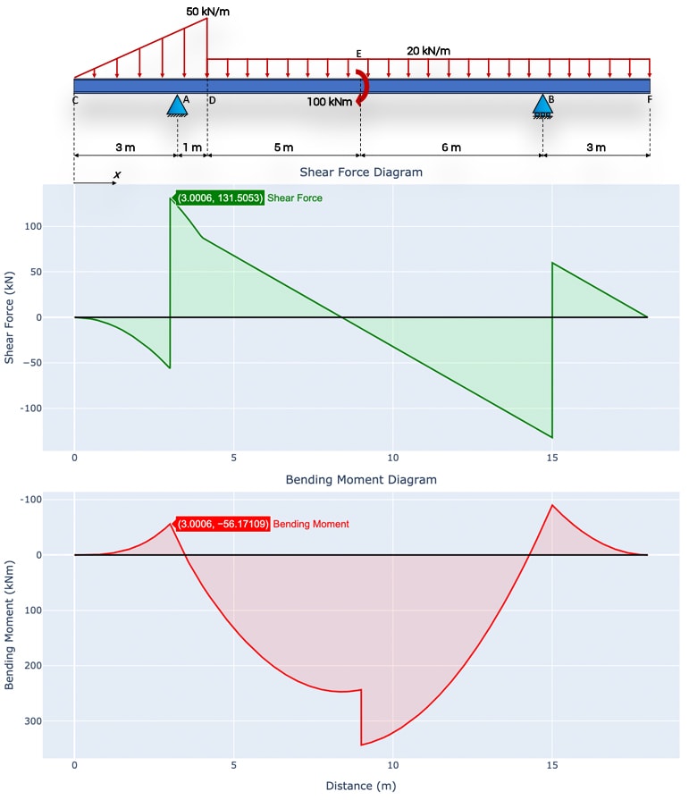
Example of drawing a shear and moment diagram graphically for a simply supported beam with a concentrated moment and linearly distributed load. I recommend ... Step 3: Using the shear force diagram, construct the bending moment diagram. You are trying to construct the moment diagram by jumping in the middle of the process without completing the basic steps (1 . It's because the shear diagram is triangular under a uniformly distributed load. Chapter-4 Bending Moment and Shear Force Diagram S K Mondal's Shear force: At a section a distance x from free end consider the forces to the left, then (V x) = - P (for all values of x) negative in sign i.e. the shear force to the left of the x-section are in downward Dr. M.E. Haque, P.E. Beam Reactions, Shear and Moment (Page 7 of 12) w L Sym. 2 / 8 - w x2 /2 w x2 /2 P 1 L / 4 P 2 x w L / 2 + P 1 / 2 MOMENT DIAGRAMS Fig. 1 Fig. 2 Fig. 3 Algebraic summation of coordinates of these three moment diagrams will produce the final moment diagram.
Moment diagrams are similar to shear diagrams, use them to find the location and value of the maximum positive and negative moment, or the moment at any specific location. The easiest and fastest way to construct a moment-diagram is by using the areas of the regions in the shear-diagram. Shear and moment diagrams and formulas are excerpted from the Western Woods Use Book, 4th edition, and are provided herein as a courtesy of Western Wood Products Association. Introduction Notations Relative to “Shear and Moment Diagrams” E = modulus of elasticity, psi I = moment of inertia, in.4 L = span length of the bending member, ft. R = span length of the bending member, in. M ... Free online beam calculator for generating the reactions, calculating the deflection of a steel or wood beam, drawing the shear and moment diagrams for the beam. This is the free version of our full SkyCiv Beam Software. This can be accessed under any of our Paid Accounts, which also includes a full structural analysis software. Moment-Shear Diagram Calculator Tool : For complex beams with more than a couple loads, determining moment and shear diagrams is very difficult. Thus, most structural engineers will use a beam analysis tool to calculate moments and shear. A basic one is avaible for mobile devices. The tool can generate the moment and shear diagram, and give ...
Shear Load And Bending Moment Diagrams
BEAM DIAGRAMS AND FORMULAS Table 3-23 (continued) Shears, Moments and Deflections 13. BEAM FIXED AT ONE END, SUPPORTED AT OTHER-CONCENTRATED LOAD AT CENTER
How To Draw Shear Force And Bending Moment Diagram In Case Of Cantilever Beam Daily Engineering
When constructing shear and moment diagrams, the sign convention is important so viewers will know what direction the beam is bending or shearing. Generally, it is assumed that a positive moment causes a beam to bend downward as shown in the diagram. A positive shear will skew the beam with the left side going up and the right going down, as shown. Each textbook can have different conventions ...

Bending Shear And Moment Diagram Graphical Method To Construct Shear Ppt Download
Setting the bending diagrams of beam. Calculate the reactions at the supports of a beam. Bending moment diagram (BMD) Shear force diagram (SFD) Axial force diagram. Invert Diagram of Moment (BMD) - Moment is positive, when tension at the bottom of the beam.
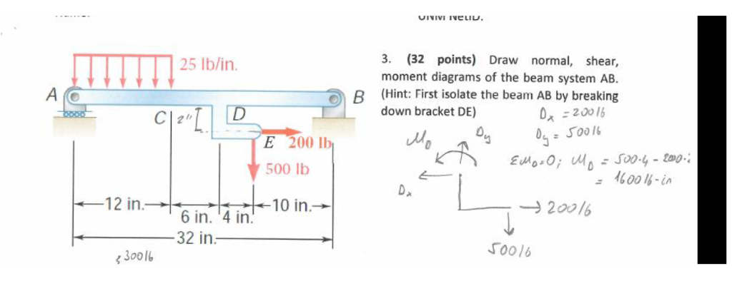
Solved Draw The Normal Shear And Moment Diagrams Of The Chegg Com
Check out http://www.engineer4free.com/structural-analysis for more free structural analysis tutorials. The course covers shear force and bending moment diag...

Drawing Shear And Moment Diagrams For Beam Youtube
Problem 403 Beam loaded as shown in Fig. P-403. [collapse collapsed title="Click here to read or hide the general instruction"]Write shear and moment equations for the beams in the following problems. In each problem, let x be the distance measured from left end of the beam. Also, draw shear and moment diagrams, specifying values at all change of loading positions and at

A Displacement Response B Bending Moment Diagram And C Shear Download Scientific Diagram
Download the DegreeTutors Guide to Shear and Moment Diagrams eBook. 📓. This is a problem. Without understanding the shear forces and bending moments developed in a structure you can’t complete a design. Shear force and bending moment diagrams tell us about the underlying state of stress in the structure. So naturally they’re the starting ...

Shear Force And Bending Moment Diagrams Download Scientific Diagram
Shear and bending moment diagrams depict the variation of these quantities along the length of the member. Proceeding from one end of the member to the other, sections are passed. After each successive change in loading along the length of the member, a FBD (Free Body Diagram) is drawn to determine the equations express-ing the shear and ...
The Ultimate Guide To Shear And Moment Diagrams Degreetutors Com
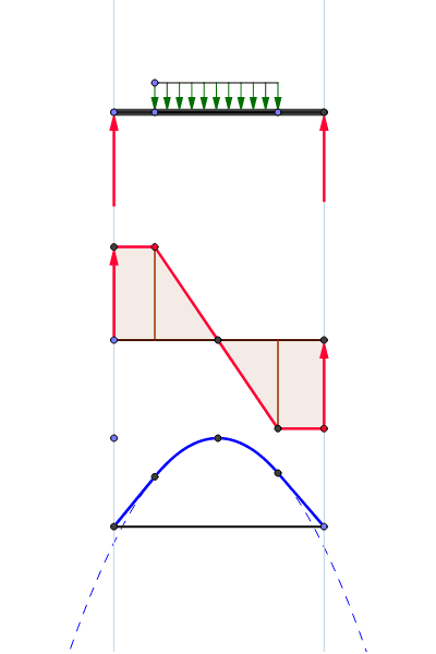
Shear and Moment Diagrams Consider a simple beam shown of length L that carries a uniform load of w (N/m) throughout its length and is held in equilibrium by reactions R1 and R2. Assume that the beam is cut at point C a distance of x from he left support and the portion of the beam to the right of C be removed. The portion removed must then be replaced by vertical shearing
Moment Diagram Engineering360
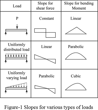
If the shear diagram is a parabola, the moment diagram will be a cubic. 4) You can tell if a triangular shear diagram should "turn into" a "skinny" parabola or a "fat" parabola by using the calculus: The value at any point on any diagram "turns into" (integrates into) the slope of the next diagram.
1
Shear and Moment Diagrams for Frames A frame is a structure composed of several members that are either fixed-or pin-connected at their ends. It is often necessary to draw shear and moment diagrams to design frames. Shear and Moment Diagrams for Frames Procedure for analysis-the following is a

Draw The Shear Diagram For Cantilever Beam In 2021 Bending Moment Beams Diagram
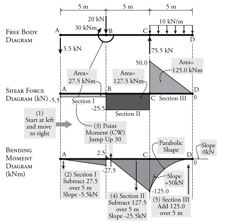
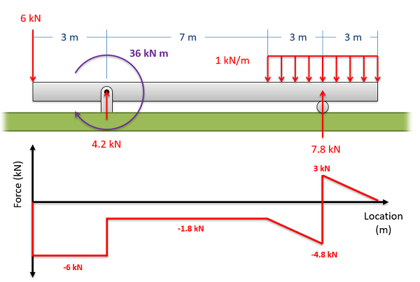
You can just ignore point C when drawing the shear force diagram. When drawing the bending moment diagram you will need to work out the bending moment just before and just after point C: Just before: bending moment at C = 3·30 - 1·40 = 50Nm. Just after: bending moment at C = 3·30 - 1·40 - 20 = 30Nm.
Shear Force And Bending Moment Diagram Practice Problem 4 Youtube
Shear and bending moment diagrams are analytical tools used in conjunction with structural analysis to help perform structural design by determining the value of shear force and bending moment at a given point of a structural element such as a beam.These diagrams can be used to easily determine the type, size, and material of a member in a structure so that a given set of loads can be ...
Loads Shear Force Diagram S F D And Bending Moment Diagram Download Scientific Diagram
Shear Diagram: Moment Diagram: 1. Point loads cause a vertical jump in the shear diagram. The direction of the jump is the same as the sign of the point load. 2. Udl result in a straight, sloped line on the shear diagram. 3. The shear diagram is horizontal for distances along the beam with no applied load. 4.
Shear And Bending Moment Diagram Distributed Load Geogebra
PDF_C8_b (Shear Forces and Bending Moments in Beams) Q6: A simply supported beam with a triangularly distributed downward load is shown in Fig. Calculate reaction; draw shear force diagram; find location of V=0; calculate maximum moment, and draw the moment diagram. 6k/ft 9 ft RA = (27k)(9-6)/9= 9k A B F = (0.5x6x9) = 27k x = (2/3)(9) = 6 ft
Shear Force And Bending Moment Diagrams Graphical Method Slide Share

Drawing Bending Moment Diagrams Effectively Mechanicalbase
Exercise Shear Force Bending Moment Diagrams Solution Tu Delft Ocw

Shear Force And Bending Moment Diagram Practice Problem 3 Youtube
Mechanics Map Shear And Moment Diagrams
Shear Moment Diagrams The Best Guide To Using Them Mentored Engineer
Shear Load And Bending Moment Diagrams
Shear Force And Bending Moment Diagram Calculator Degreetutors Com

Relationship Between Intensity Of Load Shear Force And Bending Moment

Shear Force And Bending Moment Diagram Practice Problem 2 Youtube Shear Force Bending Moment Diagram Design

Shear And Moment Diagram Wikipedia

Moment Diagrams Constructed By The Method Of Superposition Mo Civil Engineering
Shear And Moment Diagram Example 3 Mechanics Of Materials Youtube
Shear Force And Bending Moment Diagrams Sfd Bmd

Bending Moment And Shear Force Diagram Using 100 Per Cent Structural Download Scientific Diagram
Definition Of Shear And Moment Diagrams Chegg Com

Mechanics Ebook Shear Moment Diagrams

Shear Force And Bending Moment Diagrams Wikiversity

Shear Force And Bending Moment Diagrams Along The Base Of The Footing Download Scientific Diagram

Bending Moment And Shear Force Diagram For Overhanging Beam Bending Moment Shear Force Structural Analysis
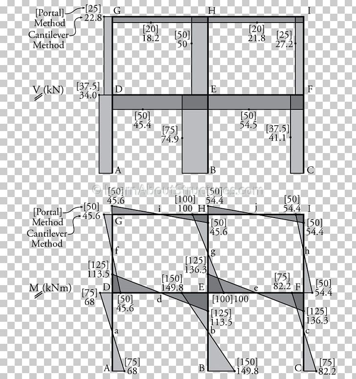
Shear And Moment Diagram Shear Force Portal Frame Bending Moment Png Clipart Angle Architectural Engineering Area
0 Response to "35 moment and shear diagram"
Post a Comment