38 guitar preamp circuit diagram
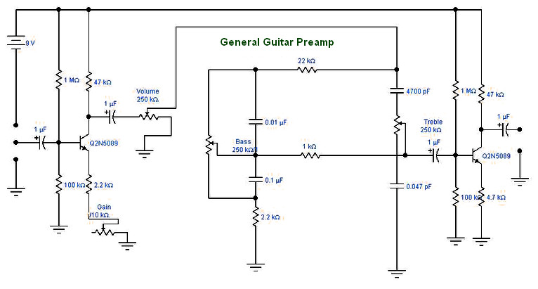
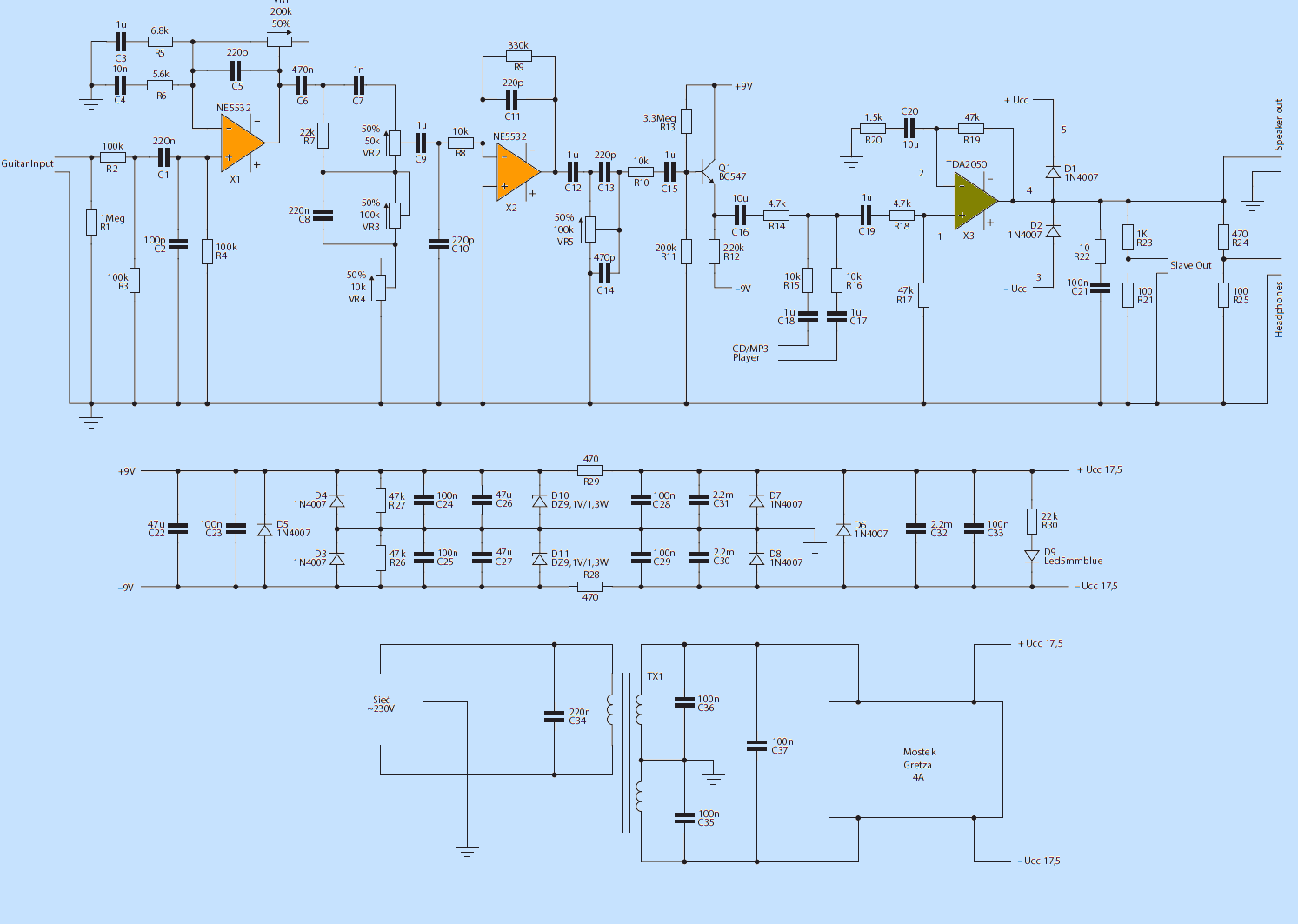
Circuit : Andy Collinson Email : Description An electric guitar pre-amp with tone controls using dual supplies. The guitar pickup is high impedance, therefore good quality screened cable must be used between guitar pickup and the preamp. Any guitar amplifier consists of three main circuits, which we will discuss below: Volume; Distortion; Tone . Guitar Amplifier Schematic and Circuits . Figure 1. Guitar amplifier schematics The Tone Circuit. The first stage of the amp is the tone circuit, which uses a dual JFET-input op-amp IC, the TL072. As you'll see in the schematic, we have ...
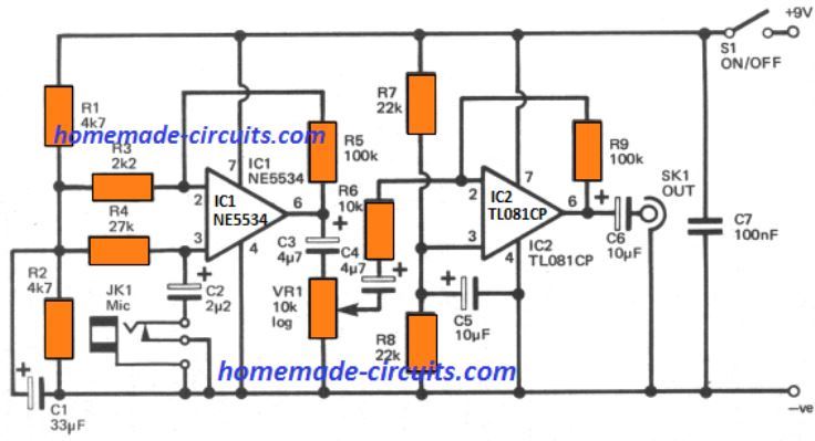
Make This Diy Contact Mic Circuit Homemade Projects. Piezo preamps make this diy contact mic circuit preamp experiment cigar box nation circuitlab the mint buffer microphone hi z amplifier lab3 laboratory for experimental discrete fet guitar acoustic pickup yet again guitarnutz 2 mpb1 918 wiring diagram bartolini passive humbucker help page 6 diyaudio simple mpxtbt agmpb b v t pickups fishman ...
.png)
Guitar preamp circuit diagram
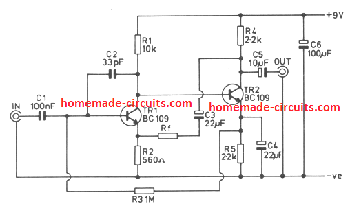
Guitar amplifier circuit diagram. Guitar Amplifier Convert Hawain To An Electric. Ad Your go-to amp for electric guitar bass and acoustic guitar. The characteristics of the circuit as shown in figure 1. This circuit has some advantages such as it will work under tough conditions very simple and has high input impedance. He is a guitar DIYer and ... Diy Amplifier. Electrical Projects. Guitar Effects Pedals. Circuit Diagram. Cool Tech. Ham Radio. TweakTone Delay Circuit for DIY Guitar Effects - PT2399 900MS. The TweakTone Delay is a PT2399-based digital delay with highly filtered repeats and the possibility of very long delay times. mahdijeddee. This diagram from Richard Kuehnel's Vacuum Tube Circuit Design: Guitar Amplifier Power Amps shows the ultra-linear taps connected to the power tube screens: The problem is ultra-linear operation reduces power tube distortion which usually sounds better than preamp distortion .
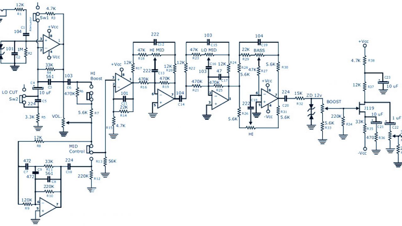
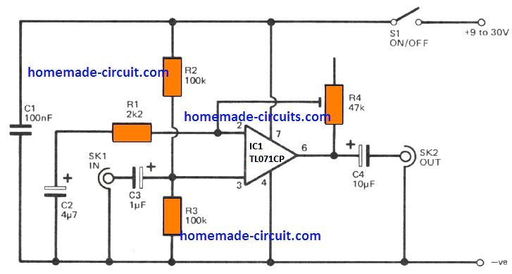
Guitar preamp circuit diagram. Preamplifier Guitar Control Circuit. Posted Wednesday, January 18, 2012. The circuit has been designed for the purpose of creating a portable unit of preamplifier that would function as standalone control for gutitars. TL062 - a low power JFET dual operational amplifier where each op-amp incorporates well matched, high voltage JFET and ... Description. A preamplifier circuit suitable for high impedance type electric guitar pickups is given here.The circuit is based on a uA 741 op-amp (IC1).The IC1 is wired as a non-inverting amplifier.The POT R1 can be used as a volume controller.The POT R6 can be used as tone controller.The switch S1 is used to produce "brilliant" or "soft" tonal effects. The circuit takes any standard guitar pickup as input. It provides two distinct output signals. Description of Electric Guitar Preamp Circuit:-The use of pickup attached to headstock to extract signals from guitar is a common practice and a circuit diagram for the same is shown in the figure 1. How to Make Guitar Amp Circuit - Tea2025b: Most people building guitar amp based on the LM386 IC which is noise prone or the TDA2030 lack of sound. Although they are cheap they are not good enough to produce the best of a basic guitar amp. So we are going to use another IC called TEA2025B wh…
Diagrams for older version of Preamps (Pre-June 2015): Basic 3B Basic module with pots. Kitchen Sink 3B installation. This shows the preamp with all the bells and whistles including an active passive push pull on the volume and 2 mid frequencies on a push pull. It also has the chart of the mid frequency capacitors and shows how to set up any 2 ... Bass Guitar Preamp Pedal. Here is the circuit diagram and PCB design for relatively low cost DIY bass guitar preamp pedal uses FET K117 or equivalent. There is a bit difficult to build this kind circuit project, it's require a good knowledge in electronics. This preamp has several features for the bass guitar instrument such as attenuator ... Electric Guitar Preamplifier Here is the circuit diagram of a guitar preamplifier that would accept any standard guitar pickup. It is also versatile in that it has two signal outputs. A typical example of using a pick-up attached to a guitar headstock is shown in Fig. 1.The pickup device has a transducer on one end and a jack on the other end. Sometime around 1990 I designed this preamp circuit, and have been using it mostly unchanged ever since. In 1992 I posted a schematic of the preamp to one of the Usenet groups and the circuit became somewhat popular. The goals of the preamp are: Sounds great. Of course. Discrete FET (Field Effect Transistor) design.
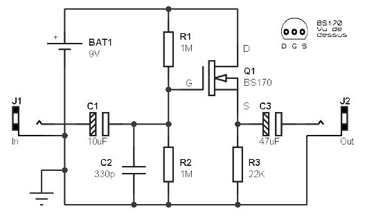
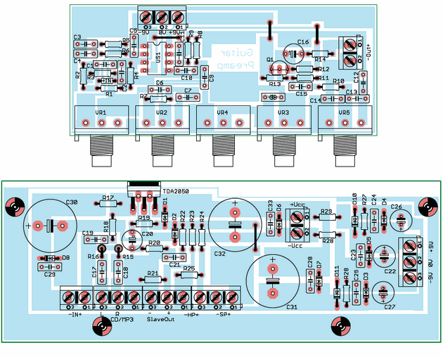
Step 2: Layout. Merging the 2 circuits found, I laid out the board of this little preamp. One thing to note is that pinout of the FET can be different, so it is wise to check the spec sheet from the manufacturer. If the pinout is the same as the ones I use, you should be able to build this project by using the same layout. Kurt began playing guitar at the age of nine in Kalamazoo, Michigan. He is a guitar DIY'er and tube amplifier designer who enjoys helping other musicians along in the endless pursuit of tone. Note that the information presented in this article is for reference purposes only. Design And Build A Guitar Preamp. For solid state guitar amplifiers, the preamp is probably the single most important part. It shapes the tone and often adds distortion that can enhance the sound you want to create. It is the "user interface" for the amp, giving a wide range of control over how the amp will sound. Guitar preamp to unplugged MacBook has hum: General Electronics Chat: 8: Aug 10, 2013: F: guitar preamp schematic theory: Datasheets, Manuals & Parts Identification: 7: Jan 6, 2013: N: My onboard bass guitar preamp design: Analog & Mixed-Signal Design: 1: Apr 6, 2012
GFS guitar preamps. Onboard effects right at your fingertips. Frequency expander, mid boost, gain boost, all wired into your guitar.
Your tube amp is made up of a preamp section and power amp section, both of these contribute to the overall tone and feel of the amp. Figure 1 on the left shows a typical tube preamp stage.This type of circuit is called a common cathode gain stage and is found in many classic Fenderamps, including the early Deluxe and Twin Reverb 'Blackface' and 'Silverface' amps.

Universal Preamplifier using Op amp LM382. The circuit diagram below shows a basic universal audio preamp using the IC LM382, which offers very low noise, low distortion, and reasonably high gain, and this circuit can be used for practically all normal audio pre-amplifier circuit applications.
.png)
B+ and circuit cground can be shared with the first preamp stage's B+ filter supply (and the ground of that filter capacitor). Fig.6 might be a place to start. The gray area is what you'll find in the amp as is. To pick values of components, see above referenced Valve Wizard advice. I'd make R10 be 1M and P1 be 1M Audio.
Ampeg A120 Schematic 120 watt RMS Rack Mount Power Amp . Ampeg AX44C Schematic 22 watt RMS 2-8 Guitar Combo . Ampeg AX70 Schematic 70 watt RMS 1-12 Guitar Combo . Ampeg AC12 Schematic 20 watt RMS 1-12 Guitar Combo . Ampeg B12N Schematic 25 watt 1-12 Guitar Piggyback Portaflex Design . Ampeg B12X Schematic 25 watt 1-12 Guitar Piggyback Portaflex Design
5 Simple Preamplifier Circuits Explained. As the name suggests a preamplifier circuit pre-amplifies a very small signal to some specified level that can be further amplified by an attached power amplifier circuit. It basically acts like a buffer stage between the input small signal source and a power amplifier.

Schematics. Here is a list of the schematics that are exclusive to this site. We created several and we have redrawn some schematics that were already available on the internet for readability or ease of use (these needed an easier-to-read format, corrections or part identifiers). Many of these schematics include "modernization" that are ...
This is a A/B Box switch pedal schematic with two inputs and one output and featured with dual operational amplifier modules. This circuit was designed by Rick Barker. This A/B Box effect was originally designed for switching between different harmonica mics. This A/B Box featured low noise dual preamp for better performance.
Figure 2 the circuit diagram of Guitar Preamplifier - over drive. The first signal section will be coupling through capacitor-C2 to a grid of V1/2, which is the final preamplifier. Then coupling through capacitor -C3 to VR3, Which acts as the volume to adjust the output level of J3. To application to headphone or guitar power amplifier in ...

Here is the circuit diagram and PCB design for relatively low cost DIY bass guitar preamp pedal uses FET K117 or equivalent. There is a bit difficult to build this kind circuit project, it's require a good knowledge in electronics.

I've drawn a schematic for a circuit that should do the job (right). I built the circuit on a plugboard and tested with a piezo pickup. For the test, I ran the output into my Radio Shack amplified speaker. Wow! The high-impedance circuit works beautifully! The output into a tube guitar amp should be even better.
This diagram from Richard Kuehnel's Vacuum Tube Circuit Design: Guitar Amplifier Power Amps shows the ultra-linear taps connected to the power tube screens: The problem is ultra-linear operation reduces power tube distortion which usually sounds better than preamp distortion .
Diy Amplifier. Electrical Projects. Guitar Effects Pedals. Circuit Diagram. Cool Tech. Ham Radio. TweakTone Delay Circuit for DIY Guitar Effects - PT2399 900MS. The TweakTone Delay is a PT2399-based digital delay with highly filtered repeats and the possibility of very long delay times. mahdijeddee.
Guitar amplifier circuit diagram. Guitar Amplifier Convert Hawain To An Electric. Ad Your go-to amp for electric guitar bass and acoustic guitar. The characteristics of the circuit as shown in figure 1. This circuit has some advantages such as it will work under tough conditions very simple and has high input impedance. He is a guitar DIYer and ...


0 Response to "38 guitar preamp circuit diagram"
Post a Comment