36 ballast resistor wiring diagram
I have uploaded picture of a wiring setup found when searching for ballast resistor wiring." That should work just fine. Basically start directly to coil for full 12 volt to start, run goes through the ballast resistor to cut down the voltage to the coil when the engine is running to take the load off of the points. Dec 15, 2020 · Ignition Coil Ballast Resistor Wiring Diagram. Print the cabling diagram off plus use highlighters to be able to trace the circuit. When you use your finger or even follow the circuit together with your eyes, it is easy to mistrace the circuit. 1 trick that We use is to print the same wiring picture off twice.
Step 3. Cut a piece of wire long enough to reach from the other terminal of the ballast resistor to the "Bat", "+" or "B+" terminal of the coil. Strip 1/2 inch of insulation from each end of this wire and crimp a connector onto each end. Connect the wire to the unused terminal of the ballast resistor and to the previously identified terminal of ...

Ballast resistor wiring diagram
Ignition Coil Ballast Resistor Wiring Diagram. Find this Pin and more on Wiring Diagram Free by Wiring Forums. Led Fluorescent. Led Tubes. Rx7. Fancy Cars. Ignition Coil. Diagram. Wire. Don't bypass the ballast resistor, if you do that you'll overstress the coil. If you look in those diagrams you'll see that +12V is on B and Coil+ is on F. Between B & F is a resistance of about 2 Ohms, whilst cranking the starter 12V is applied to C and this has about 1 Ohm between C & F. I can't find the wire for the backup lights on. 1965 convertible. Any suggestions? Do the wires from the neutral Safety Switch go from the switch to under the dash the fuse box? Kevin Bankos — June 1, 2013 3:27 PM . Where is the ballast resistor located for the ignition system in a 65 mustang, 289 2 barrel. This car is burning up points fast.
Ballast resistor wiring diagram. Step 12 - Ballast Resistor Installation . The ballast resistor should be mounted in a solid location either near the ECU or on the firewall. Depending on the type of installation there are two methods for ballast resistor wiring. Connect one side of the ballast resistor to the positive (+) side of the coil. May 11, 2019 · A ballast resistor is a resistor inserted into a circuit to compensate for different changes. The coil does not go direct to earth. Mopar Ballast Resistor Wiring Diagram Basic Electronics Wiring Diagram I am planning to replace the distributor with a mallory unilite pointless distributor the instructions emphasize the necessity of either a ballast resistor […] The following diagram shows the 5 pin box with dual ballast resistor; "Start" is only hot (+12V DC) during cranking, and "run" is hot (+12V DC) from the moment you turn the key on, through crank, and after crank. Unhook the ballast resistor and find the wire that has power to it coming from the ignition. You should be able to connect your msd directly to that wire and remove the ballast resistor. I think its the blue wire. If there is two blues one may be for crank (ignition 2) and the other for crank and ignition (ignition one).
Instant start ballasts can only be wired in parallel according to the diagram on the ballast. Changing the wiring on a fluorescent light fixture from rapid start to instant start, involves changing the wiring from series to parallel. 1 Lamp Rapid Start Ballast Diagram. Jan 01, 2021 · Wiring the pertronix ballast resistor bmw 2002 installing vintage mustang for a bos only mopar forum install page 2 classic bypassing kohm coil on 71 240z no brainer question ignitor starts runs installation b new convert points to Wiring The Pertronix No Brainer Wiring Question Ballast Resistor Bmw 2002 And Other 02 Faq Installing Pertronix Vintage… Read More » This Video explains how the Ballast Resistor Works.For additional How-to Tutorials Visit our Website: http://www.howstuffinmycarworks.com Jan 04, 2016 · Description: Ignition Coil Ballast Resistor Wiring Diagram with Ignition Coil Ballast Resistor Wiring Diagram, image size 609 X 360 px, and to view image details please click the image. Here is a picture gallery about ignition coil ballast resistor wiring diagram complete with the description of the image, please find the image you need.
May 23, 2021 · A resistor wire or ballast resistor may or may not be included in the original equipment. The typical automotive ignition system prior to 1974 consisted of a coil and ballast resistor with breaker points to interrupt the current flow when a spark was needed. Diagram Wiring Diagram Ballast Resistor Ignition Coil Full Version Hd Quality … Re: 1988 OMC Ballist resistor location?? It shouldn't matter. If you look at the circuit diagram, you'll see that the A+ (thru the ballast "resistor") goes directly to the "plus" side of the coil. The ESA (output) is essentially in parallel with the points/condenser. According to the wiring diagram, the pink ballast wire goes from a red and green lead from the ignition switch, to the far right connector going thru the firewall. It then leaves the engine side of the connector, as red/green again, and goes to the positive side of the coil. When I check the voltage of this wire, at the coil, I always get a ... Ignition Coil Ballast Resistor Wiring Diagram Download. A wiring diagram is a schematic type that uses abstract illustrated symbols to show all of the components of a system. Wiring diagrams are made up of two things: symbols that represent the components of a circuit, and lines that represent the connections between them.
Electronic ignition, Crane/Allison XR700
This wiring diagram is for the 1980 and later four pin ignition module. If you have an ignition harness with five wires, just don't connect the dark green wire that would go to pin 3. I Installed a Jacobs computer ignition, and it doesn't require a ballast resistor.

Installation Diagram for Stone Line (c. 1976) // Richard Long English, born 1945
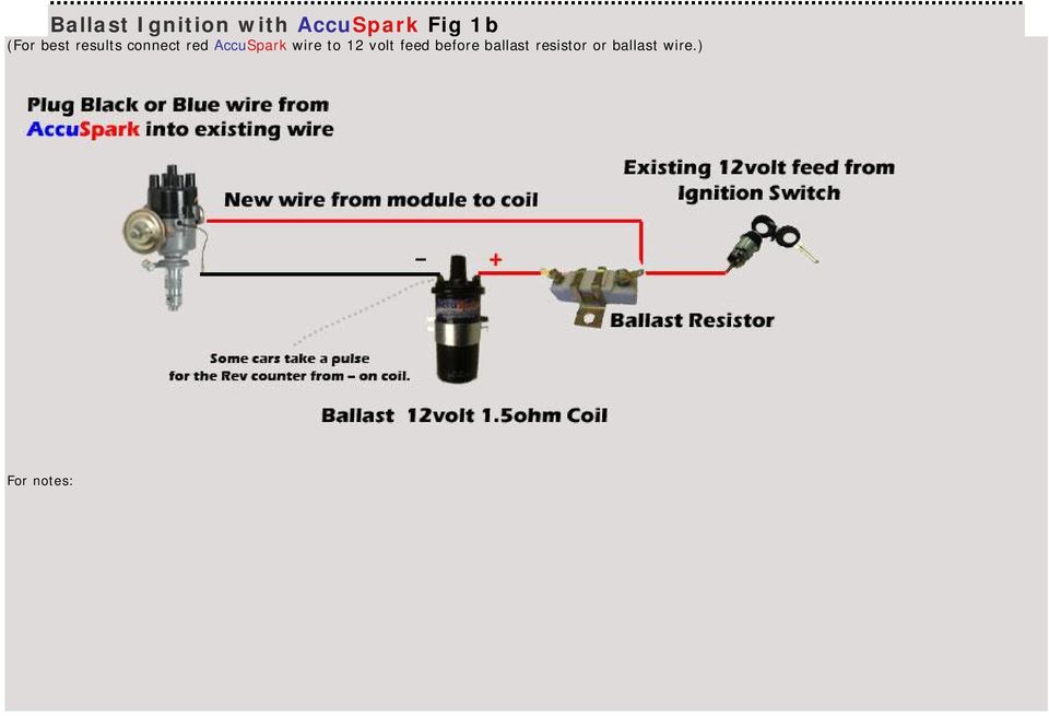
RED WIRE: If you use loom resistance wire, connect to the coil (+) terminal. If you use a ballast resistor, connect to 12 volt side of ballast resistor. GREEN WIRE: Connect to the coil (-) terminal. BROWN WIRE: Connect to engine block ground. Clean away any grease, oil and paint from the mounting surface before the con-nection is made.

Ballast Resistor 12 Volt Coil
The ballast resistor get's installed on the wire from the ignition switch to the positive side of the ignition coil and it's the wire that is hot when the key is on run not start. the start coil wire should still have 12 volts. One second and I'll pull up the wiring diagram. Ford Ignition Wiring Diagram - wiring diagram plymouth reliant ...
yellow blue and black coated wires
9. Route the blue wire to the ballast resistor. Avoid the exhaust manifolds and sharp edges, follow existing wiring harnesses if possible. 10. Disconnect the wires from both ends of the original ballast resistor. Remove the old ballast resistor and install the new ballast resistor in its place. Do not reconnect the wires. 11.

☑ Coil Ballast Resistor Wiring
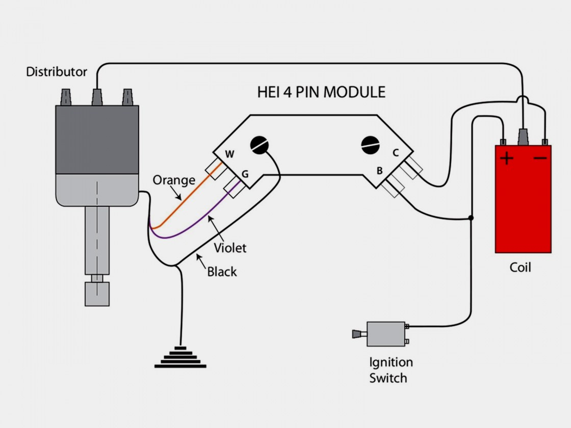
run through a ballast resistor or wire. Bypass any resistance unit to provide full 12V key ON power to the coil and module. If you set up a battery on a bench and hook up all the wires as shown you can check the spark by toggling the point lead (#5) to ground. You will see a nice hot spark out of the secondary. The circuit is quite simple and works
PCM 351 Vapor Lock Issues - Page 4
Step 4: Install Ballast Resistor. Set the ballast resistor up to the firewall and screw the clamps in place. Step 5: Connect Wires to Positive. Strip the end of the positive wire from the ignition, and connect it to the positive end of the resistor. From the other terminal on the resistor a wire goes to the positive on the coil.

Resistor Wiring Diagram / Ford Ballast Resistor Wiring ...
Ford Ballast Resistor Wiring Diagram. Print the wiring diagram off plus use highlighters to trace the signal. When you make use of your finger or perhaps the actual circuit with your eyes, it is easy to mistrace the circuit. 1 trick that We 2 to printing a similar wiring plan off twice.

Ballast resistor wiring diagram
As a matter of fact, a bad diode trio in a conventional alternator can do the same damage. 2 wiringall.com MALLORY IGNITION-+ COIL FIGURE 1 UNILITE® WIRING DIAGRAM USING BALLAST RESISTOR NOTE: The purpose of an ignition ballast resistor between the ignition switch (12V) and the ignition coil positive terminal is to restrict current flow ...

How To Bypass A Ballast — 1000Bulbs.com Blog
Mar 10, 2021 · Ballast resistor ignition troubleshooting accuspark wiring diagrams igniter and with australian rr forums resistors studebaker orange box small conversion harness tech wiki coil datsun 1200 club 65 mopar diagram full bypassing for a anything i can substitute issue 71 302 only runs in systems installing how to replace working uses 240z wire up ...
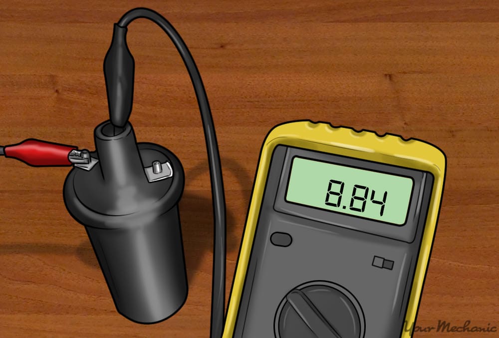
How to Test an Ignition Coil
Wiring diagram for ignition coil. Ballast resistor 12 volt ignition coil wiring diagram. Ignition coils of this type are usually a little larger than a soda can and are heavy. These coils had very simple wiring. Determine whether the coil is a 9 volt or a 12 volt coil.

Ford Ballast Resistor Wiring Diagram - Wiring Diagram
FIGURE 1 UNILITE® WIRING DIAGRAM USING BALLAST RESISTOR NOTE: The purpose of an ignition ballast resistor between the ignition switch (12V) and the ignition coil positive terminal is to restrict current flow through the ignition coil. Failure to use an ignition ballast resistor will eventually destroy the Ignition Module.

1979 MG Midget .
I can't find the wire for the backup lights on. 1965 convertible. Any suggestions? Do the wires from the neutral Safety Switch go from the switch to under the dash the fuse box? Kevin Bankos — June 1, 2013 3:27 PM . Where is the ballast resistor located for the ignition system in a 65 mustang, 289 2 barrel. This car is burning up points fast.

What Does A Ignition Ballast Resistor Do
Don't bypass the ballast resistor, if you do that you'll overstress the coil. If you look in those diagrams you'll see that +12V is on B and Coil+ is on F. Between B & F is a resistance of about 2 Ohms, whilst cranking the starter 12V is applied to C and this has about 1 Ohm between C & F.

River City II: Geometry Study (n.d.) // Bertrand Goldberg American, 1913-1997
Ignition Coil Ballast Resistor Wiring Diagram. Find this Pin and more on Wiring Diagram Free by Wiring Forums. Led Fluorescent. Led Tubes. Rx7. Fancy Cars. Ignition Coil. Diagram. Wire.
orange box and small conversion harness QUESTION | For C Bodies Only Classic Mopar Forum
Help with ballast resistor wire replacement on '67 GTO | Pontiac GTO Forum

Ballast Resistor 12v To 6v
Technical - Please help ballast resistor wiring ignition wiring | The H.A.M.B.

Marina City: Finish Diagram (n.d.) // Bertrand Goldberg American, 1913-1997

Ford Ballast Resistor Wiring Diagram - Wiring Diagram
12v Ignition Coil Ballast Resistor Wiring Diagram - Wiring ...
white animal skull on white surface

River City I, Marina City, Chicago, Illinois, Sectional Diagram (N.d.) // Bertrand Goldberg American, 1913–1997
Ford Ballast Resistor Wiring Diagram - Wiring Diagram

1979 MG Midget
blue and green thread on brown wooden shelf
brown and gray metal tools

Ford Ballast Resistor Wiring Diagram For Your Needs
Wiring Puzzle Solved – Restoration of NNF 10H

Ballast Resistor Wiring Diagram - Wiring Diagram Schema
12v Ignition Coil Ballast Resistor Wiring Diagram - Wiring ...

white pasta on white paper
Ballast Resistor Not Resisting? - Electrical - The Classic Zcar Club
how to wire up ballast resistor - CorvetteForum - Chevrolet Corvette Forum Discussion
How To Read A Ballast Wiring Diagram | Cadician's Blog

Ignition Coil Ballast Resistor Wiring Diagram | Fuse Box ...
0 Response to "36 ballast resistor wiring diagram"
Post a Comment