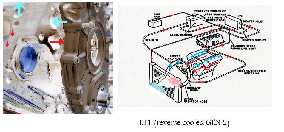
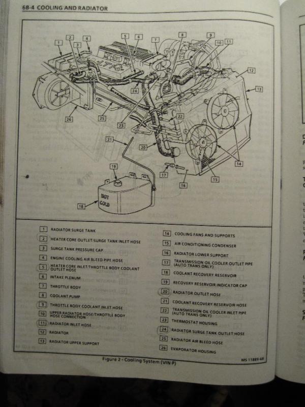
37 lt1 cooling system diagram
895 Posts. #5 · Mar 22, 2009 (Edited) On a Caprice is goes to the expansion coolant tank. The B-body, and F-body used different cooling systems. B-body had the pressure cap on the take. You your self a favor, and do the "tb-bypass". Basically, the 2 hoses that go to the TB, skip the TB, and join the hose from the tank, to the line that runs to ... The entire cooling system on the LT1 is designed to operate at lower pressures than conventional cooling systems. The maximum operating pressure in the LT1 cooling system is 15 psi for B/D-cars and 18 psi for F-cars, limited by a pressure cap. These limits are similar to other cars, but in the LT1, these maximum pressures are rarely reached.
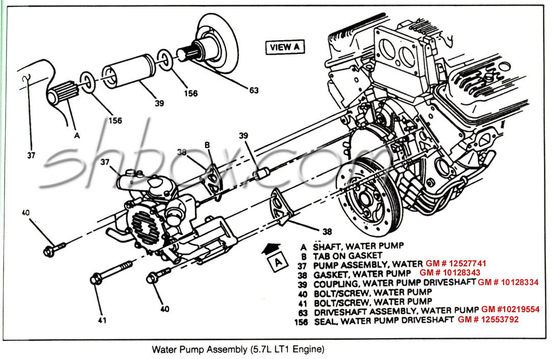
In 1992, GM introduced the LT1 engine, a revolutionary new 350 CI small block to be used in all its rear wheel drive vehicles. All of these engines from 1992 through 1997 use a reverse flow water pump that is driven directly off the camshaft.
Lt1 cooling system diagram
I would sure like to see a clearer diagram. You are right, as usual. about the hose restrictor. Specifically, the 92 Corvette LT1 uses an inline hose restrictor. part# 10157988 Stock TPI and TBI have a restrictor also. Everco part# 4894 V8 S-10 trucks can lower their coolant temps by 10 dgegrees or better using a restrictor too. Conventional cooling systems have passages in the intake manifold which allow coolant to crossover from one side of the engine to the other. In the LT1, coolant crossover occurs in the water pump, which is also where the thermostat is located. Since there are no coolant passages in the intake manifold, a major source of leaks has been eliminated. Chevy reversed the flow direction in the LT1-LT4 engines to direct the cooling system can easily over come. the direction of coolant flow is not . all coolant flow paths roughly equal in the crappy diagram below the blue.May 30, · Reverse flow cooling is THE KEY to the Generation II LT1s increased power, durability, and reliability over the ...
Lt1 cooling system diagram. 14 Jan 2015 — LT1 Based Engine Tech - 94 LT1 Cooling system diagram - Hey all, Got a 94 LT1 in an 89 S-10 and have really no idea of what hose hooks to ... Posted May 28, 2008. I attached a rather crude sketch of my cooling system and I think I have it backwards after reading this: LT1 Coolant Flow: The LT1 is completely different since it uses reverse flow cooling. The incoming coolant first encounters the thermostat, which now acts both on the inlet and outlet sides of the system. The entire cooling system on the LT1 is designed to operate at lower pressures than conventional cooling systems. The maximum operating pressure in the LT1 cooling system is 15 psi for B/D-cars and 18 psi for F-cars, limited by a pressure cap. These limits are similar to other cars, but in the LT1, these maximum pressures are rarely reached. 12 Mar 2007 — LT1 Coolant Flow: The LT1 is completely different since it uses reverse flow cooling. The incoming coolant first encounters the thermostat, ...
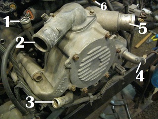
Lt1 Water Pump Hose Diagram. are three small hose fittings and two large ones on the LT1 water pump. By now have you found a link to a complete hose diagram that I. I'm trying to plumb in the coolant system, anyone have a diagram of where all these I have hoses that go to the intake, heads, water pump. I. The LT1 has no hoses on it and the 37 ... Lt1 vacuum hose diagram as well as need help lt1 water pump in addition 94 lt1 engine diagram in addition lt1 cooling fan wiring along with symptoms of bad intake air temperature iat sensor moreover chevy silverado cooling system diagram moreover overhead valve as well as airconditioningservice as well as keeping larry dixons lt4 powered nova ... 26 Aug 2009 — LT1/LT4 Tech - cooling system diagram - I need to know how and where all and i mean all the cooling hoses go becuase i can not seem to find ... Chevy reversed the flow direction in the LT1-LT4 engines to direct the cooling system can easily over come. the direction of coolant flow is not . all coolant flow paths roughly equal in the crappy diagram below the blue.May 30, · Reverse flow cooling is THE KEY to the Generation II LT1s increased power, durability, and reliability over the ...
Conventional cooling systems have passages in the intake manifold which allow coolant to crossover from one side of the engine to the other. In the LT1, coolant crossover occurs in the water pump, which is also where the thermostat is located. Since there are no coolant passages in the intake manifold, a major source of leaks has been eliminated. I would sure like to see a clearer diagram. You are right, as usual. about the hose restrictor. Specifically, the 92 Corvette LT1 uses an inline hose restrictor. part# 10157988 Stock TPI and TBI have a restrictor also. Everco part# 4894 V8 S-10 trucks can lower their coolant temps by 10 dgegrees or better using a restrictor too.

Pdf Design Of A Thermoelectric Generator For Waste Heat Recovery Application On A Drivable Heavy Duty Vehicle Semantic Scholar
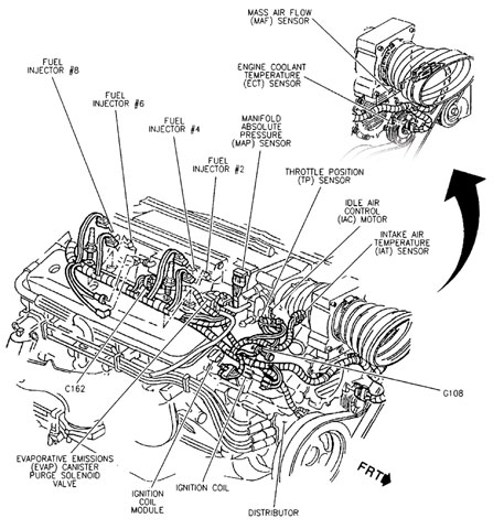


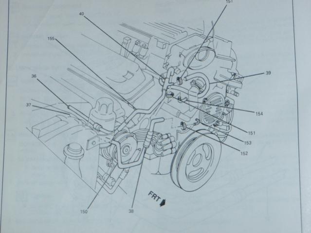






0 Response to "37 lt1 cooling system diagram"
Post a Comment