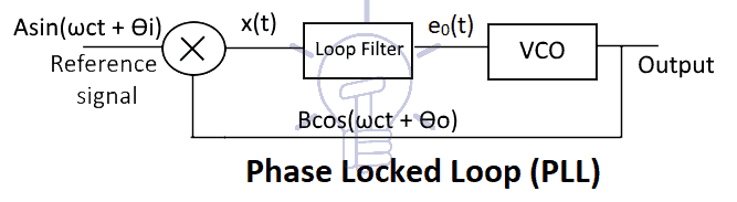
38 phase lock loop block diagram
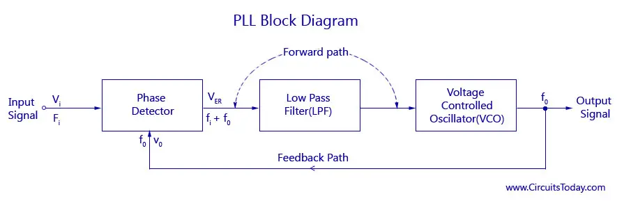
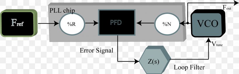
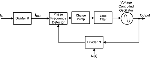
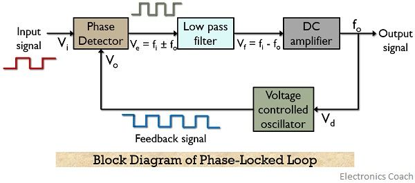
Phase locked loop (pll) is one of the vital blocks in linear systems. Phase locked loop block diagram. (11.35) f ref = f d = f out n. Before the invention of ic pll, systems were very complex and costly for use in most consumer & industrial systems. Basics of phase lock loop3. Now pll ics are fabricated at a very low cost. The block diagram and connection diagrams are shown in the figure below. The block diagram consist of a phase detector which acts as a phase comparator, an amplifier, and a low pass filter with the combination of the resistor (3.6 kilo ohm) and capacitor C2. The output of the amplifier is fed back to the VCO.
In this video, i have explained Phase Lock Loop by following outlines:1. Phase Lock Loop2. Basics of Phase Lock Loop3. Need of Phase Lock Loop 4. Block Diagr...
Phase lock loop block diagram
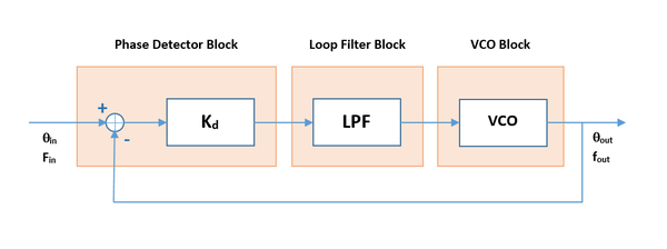
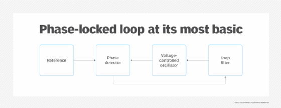
Phase Locked Loop Block Diagram!" ÖN Ref Div Loop Filter VCO Phase Locked Loops (PLL) are ubiquitous circuits used in countless communication and engineering applications. Components include a VCO, a frequency divider, a phase detector (PD), and a loop lter. Niknejad PLLs and Frequency Synthesis. A Phase Locked Loop Working is basically a closed loop system designed to lock the output frequency and phase to the frequency and phase of an input signal. Phase Regulator P Calc Q Calc Q-V Droop and V Regulator V mag calc PWM Generator Vab Vcb i a i c I p i Q P V mag V command V a Vb V c Fig. 1. Block diagram of inverter control. microgrid should continue to serve its loads without disruption. The microgrid must also be able to resynchronize with the grid when the condition that initiated ...
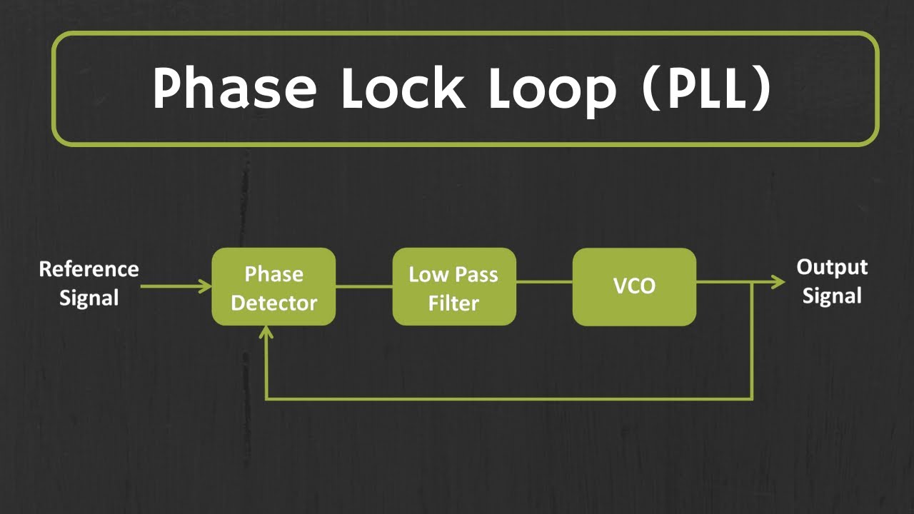
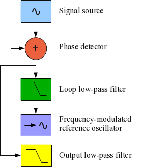
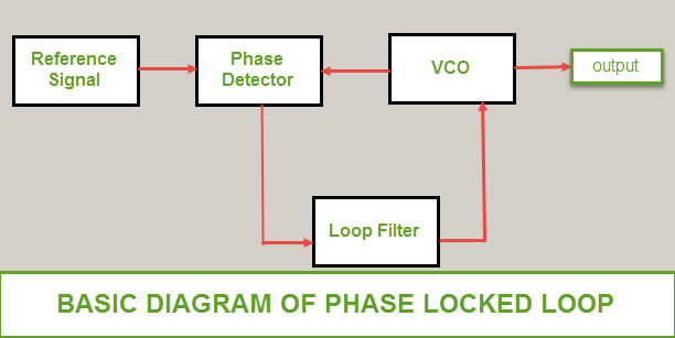
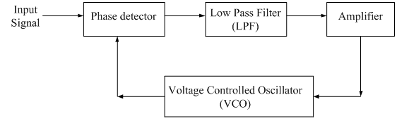
Phase lock loop block diagram. Block Diagram of PLL ... The output of a phase detector is applied as an input of active low pass filter. Similarly, the output of active low pass filter is ... The phase locked loop or PLL is a particularly useful circuit block that is widely used in radio frequency or wireless applications. In view of its usefulness, the phase locked loop or PLL is found in many wireless, radio, and general electronic items from mobile phones to broadcast radios, televisions to Wi-Fi routers, walkie talkie radios to professional communications systems and vey much more. 4 CD4046B Phase-Locked Loop: A Versatile Building Block for Micropower Digital and Analog Applications 3 CD4046B PLL Technical Description Figure 2 shows a block diagram of the CD4046B, which has been implemented on a single monolithic integrated circuit. The PLL structure consists of a low-power, linear VCO and two ... phase locked Loop (PLL) is then used to lock the VCO. The typical PLL block diagram as in figure 2 shows a crystal oscillator frequency divided by R to ...
Block Diagram And Working Principle Of PLL ... The phase-locked loop consists of a phase detector, a voltage controlled oscillator and, in between them, a low ...High: Low Describe the basic block diagram of the phase locked loop (PLL). A phase locked loop is basically a closed loop system designed to lock the output frequency and phase to the frequency and phase of an input signal. They are used in applications such as frequency synthesis, frequency modulation/demodulation, AM detection, tracking filters, FSK ... Block diagram: x(t) PFD QA QB VDD Cp I1 I2 S1 S2 VCO y(t) Fig. 2.2-20 The charge pump and capacitor Cp serve as the loop filter for the PLL. The charge pump can provide infinite gain for a static phase shift. Block diagram — A phase-locked loop or phase lock loop (PLL) is a control system that generates an output signal whose phase is related to the phase of an ...Structure and function · Applications · Block diagram · Elements
15 Phase Locked Loop Block Diagram. The design of a pll typically involves determining the type of loop required, selecting the proper laplace representation of diagram in figure 11. The connection diagram of a se/ne 566 vco is shown in the gure. Phase-Locked Loops - National Instruments from www.ni.com Shows… Phase Regulator P Calc Q Calc Q-V Droop and V Regulator V mag calc PWM Generator Vab Vcb i a i c I p i Q P V mag V command V a Vb V c Fig. 1. Block diagram of inverter control. microgrid should continue to serve its loads without disruption. The microgrid must also be able to resynchronize with the grid when the condition that initiated ... A Phase Locked Loop Working is basically a closed loop system designed to lock the output frequency and phase to the frequency and phase of an input signal. Phase Locked Loop Block Diagram!" ÖN Ref Div Loop Filter VCO Phase Locked Loops (PLL) are ubiquitous circuits used in countless communication and engineering applications. Components include a VCO, a frequency divider, a phase detector (PD), and a loop lter. Niknejad PLLs and Frequency Synthesis.
Phase Locked Loop Pll Its Operation Characteristics Application

Phase Locked Loop Wikipedia

Phase Locked Loop Informatika Komputer 2 3045 P2k Um Surabaya Ac Id
What Is Phase Lock Loop Pll How Phase Lock Loop Works Pll Explained Youtube
2

Pdf Digital Implementation Of Modified Phase Locked Loop Based Harmonic Extraction For Shunt Active Filter Semantic Scholar
Rf Tutorial Lesson 15 Exploring Phase Locked Loops Emagtech Wiki

Demo Phase Locked Loop

Block Diagram Electronic Circuit Analog To Digital Converter Circuit Diagram Phase Locked Loop Analog Circuits Electronics Text Plan Png Pngwing

Phase Locked Loop Wikipedia
1
Understanding Phase Locked Loops
Transmitter Building Blocks
Pll Implementation

Phase Locked Loop Design And Construction Elliot Nwaobi Elec 163

Phase Locked Loop A Fundamental Building Block In Wireless Technology

Lab 5 Digital Phase Locked Loop Pll Matlab Part

The Working Of Phase Detector In Pll Adsantec

Classece4332fall15grouppll Uva Ece Bme Wiki
1
Block Diagram Electronic Circuit Analog To Digital Converter Circuit Diagram Phase Locked Loop Png Clipart Analog

Final Project Phase Lock Loop Design Shane Mcnamara Elec
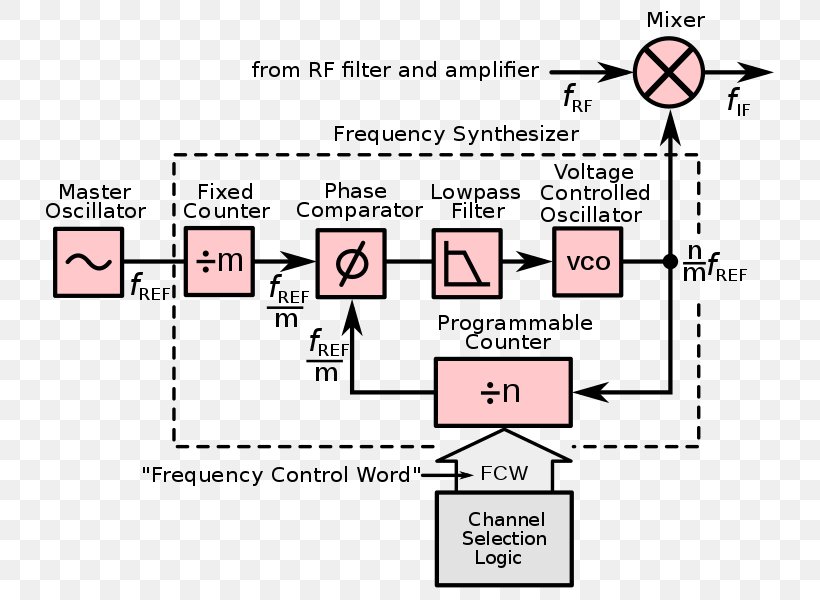
Phase Locked Loop Frequency Synthesizer Information Adpll Document Png 755x600px Phaselocked Loop Area Automatic Frequency Control
Phase Locked Loops Block Diagram Working Operation Design Applications
Electronics Frequency Synthesizer Phase Locked Loop Voltage Controlled Oscillator Sound Synthesizers Png 1600x502px Electronics Block Diagram
Reference Clock Phase Lock Loop Ni High Speed Digitizers Ni Scope 16 1 Help National Instruments

Pll Basics From Asics To Socs A Practical Approach Book

General Block Diagram Of Adpll Beginning Of All Digital Phase Locked Download Scientific Diagram
Phase Locked Loops
Phase Locked Loop Operating Principle And Applications

Simulink Exercises For Digital Communications A Discrete Time Approach By M Rice
Clock Generation Using Pll Frequency Synthesizers Digikey
What Are Phase Locked Loops Pll Definition Block Diagram Working And Applications Of Phase Locked Loops Electronics Coach

Phase Locked Loop Based Techniques For Compensation Of Voltage Based Power Quality Issues In Distribution System
What Is A Phase Locked Loop Pll
Phase Locked Loop Analog Integrated Circuits Electronics Tutorial

Phase Locked Loop System Working And Applications
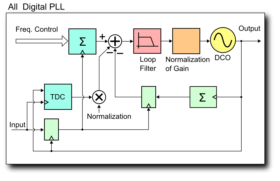
File All Degital Pll Block Diagram 2 Png Wikimedia Commons
0 Response to "38 phase lock loop block diagram"
Post a Comment