39 x-ray tube diagram
13 Jul 2020 — Various x-ray tube diagrams for teaching. ADVERTISEMENT: Supporters see fewer/no ads. Cathode and focal spot. An x-ray tube functions as a specific energy converter, receiving electrical energy and converting it into two other forms of energy: x-radiation (1%) and heat (99%). Heat is considered the undesirable product of this conversion process; therefore x-radiation is created by taking the energy from the electrons and converting it into photons.This very specific energy conversion takes place in ...
8 Apr 2013 — Diagram - X-ray tube. Case contributed by Dr Matt Skalski ◉. Diagnosis not applicable. Diagnosis not applicable. Edit case ShareAdd to.

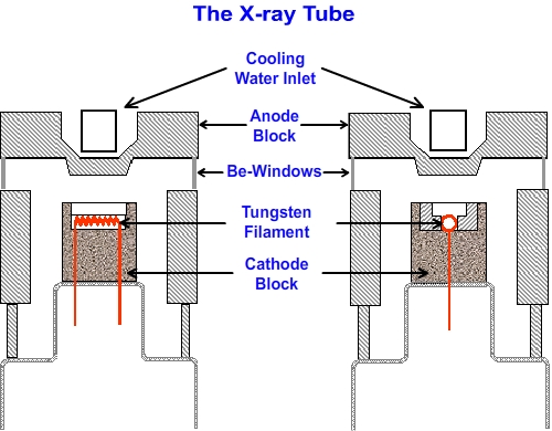
X-ray tube diagram
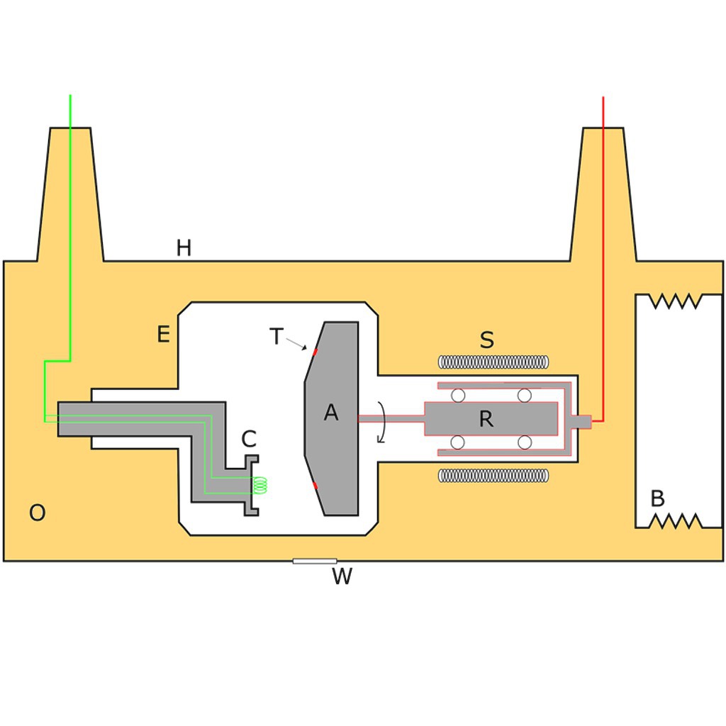
28 Apr 2015 — The X-ray tube contains two principal elements: cathode: provides a source of electrons anode: acts as the target for electrons and releases ... X-ray tube design • Filament is heated, releasing electrons via thermionic emission (V f ~ 10V, I f ~ 4A, resulting in T>2000oC) • X rays are produced by high-speed electrons bombarding the target • Typically < 1% of energy is converted to x rays; the rest is heat Figure 2-1 (a). Schematic diagram of x-ray tube and circuit V f X-ray tube ... 17 Jan 2010 — A: anode · B: expansion bellows (provide space for oil to expand) · C: cathode (and heating-coil) · E: tube envelope (evacuated) · H: tube housing ...
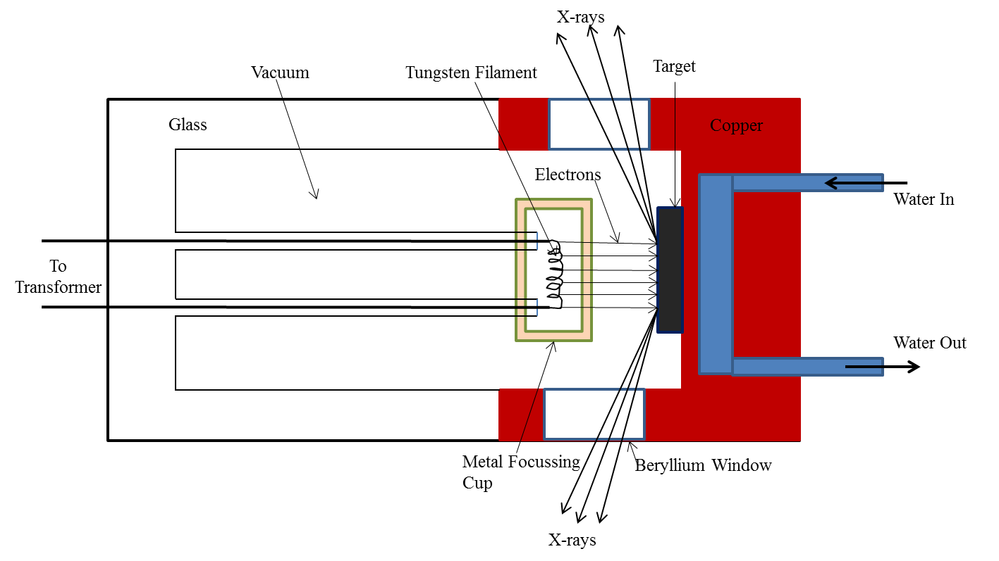
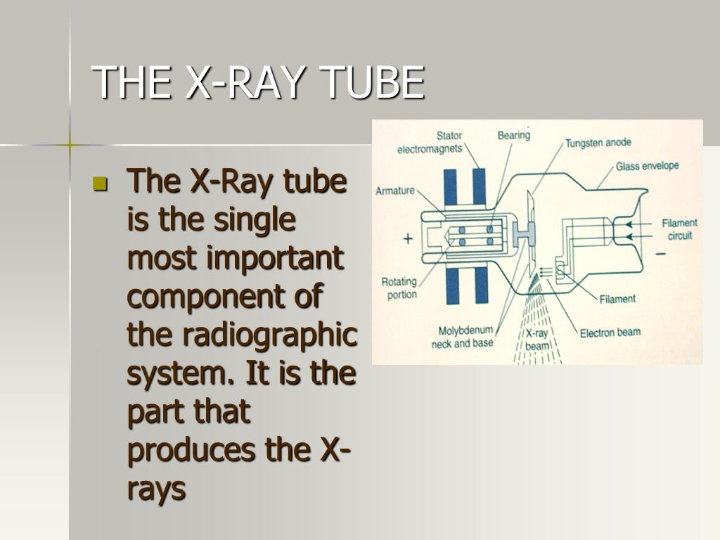
X-ray tube diagram. Radiology Schools. X-Ray Tube Diagram | Standard stationary anode x-ray tube; diagram in longitudinal section .. Q1. The simplified diagram shows a modern X-ray tube. (a) For each of the labelled parts, state what it is and explain its purpose. A is a glass tube It is sealed and evacuated. It allows electrons to travel unimpeded. B is a rotating anode Rotation of the anode spreads out the heated area on the target It is made of metal (tugsten or ... Introduction. Chapter 1 provided a general discussion of the x-ray tube head assembly and the function of the major parts of the design. Chapter 4 discussed the components of the x-ray circuit and the events that lead to the production of x-rays in the x-ray tube. This chapter examines the x-ray tube itself (), its general construction, and how it works. potential of the x-ray tube, or the kilovoltage that will be flowing through the tube once the exposure is made. Next is the exposure switch, or the timing circuit, which is used to complete the x-ray exposure. It regulates the length of the exposure, and it’s where the tech starts and the .
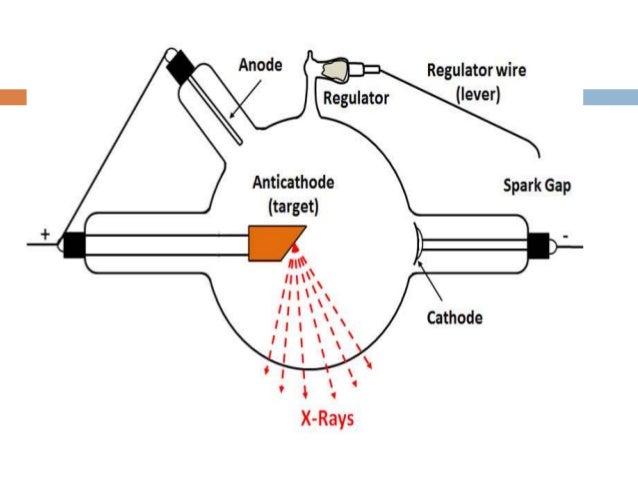
An X-ray tube is a vacuum tube that converts electrical input power into X-rays. The availability of this controllable source of X-rays created the field of ... X-ray tube diagrams. Case contributed by Dr Matt Skalski . Diagnosis not applicable. Diagnosis not applicable. From the case: X-ray tube diagrams. Schematics of a conventional X-ray tube: the electrons (e − ) are emitted from the cathode and collected at the anode releasing X-ray radiation [12]. · Figure 1 ... Max. power of the tube: P=kV.mA (100x300=30kW) Max anode heat capacity HU=kV.mAs (100x1000=100kHU) 1HU=1.4 Joules X-ray Tube characteristics: Using of single exp. chart Fine focus and Large focus effects X-ray image resolution depends on the size of the X-ray tube focal spot
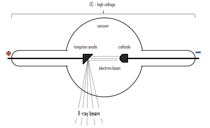
As the DC voltage (anode-to-cathode of the x-rays tube) is increased, the wavelength of x-rays decreases. Same tubes now operate at more than a million volts. Block Diagram of X-Rays machine. Figure 2: Block Diagram of X-Ray Operation/Working of X-Ray Machine High voltage source and high voltage transformer Q1. The simplified diagram shows a modern X-ray tube. (a) For each of the labelled parts, state what it is and explain its purpose. (i) the direction of the electron beam, (ii) the direction of the useful X-ray beam. Q2. (a) The diagram shows a rotating-anode X-ray tube. Complete the labelling of the three numbered arrows in the diagram. the picture, you can see the technologist handling the x-ray tube. She is manipulating the field size by adjusting a device called the “collimator” which is attached to the x-ray tube housing. The rectangular looking device just above the collimator is the housing for the x-ray tube. The diagram on the right shows the x-ray tube by itself . 17 Jan 2010 — A: anode · B: expansion bellows (provide space for oil to expand) · C: cathode (and heating-coil) · E: tube envelope (evacuated) · H: tube housing ...
X-ray tube design • Filament is heated, releasing electrons via thermionic emission (V f ~ 10V, I f ~ 4A, resulting in T>2000oC) • X rays are produced by high-speed electrons bombarding the target • Typically < 1% of energy is converted to x rays; the rest is heat Figure 2-1 (a). Schematic diagram of x-ray tube and circuit V f X-ray tube ...
28 Apr 2015 — The X-ray tube contains two principal elements: cathode: provides a source of electrons anode: acts as the target for electrons and releases ...

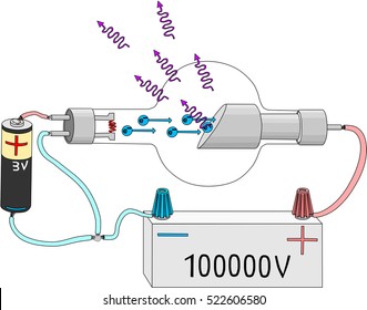
Figure 7 7 Vacuum X Ray Tube The Image On The Left Shows A Schematic How Electrons Are Accelerated From The Cathode To The Anode To Genereate X Ray Photons The Image On The Right

National Museum Of Health And Medicine Nmhm Discovery Of The X Ray A New Kind Of Invisible Light Rontgen And The Discovery
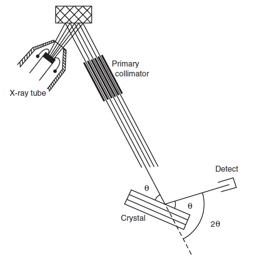
Figure 8 1 3 Schematic Diagram Of A Wavelength Disper Sive X Ray Spectrometer Components Including X Ray Tube Specimen Primary Collimator Diffracting Crystal Angle 8 And Detector Drawing Courtesy Of Kanare Infinity For Cement

X Rays Definition Of X Rays By Medical Dictionary Radiology Student Radiology Humor Rad Tech Student











0 Response to "39 x-ray tube diagram"
Post a Comment