40 fe-c phase diagram
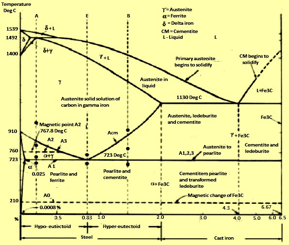
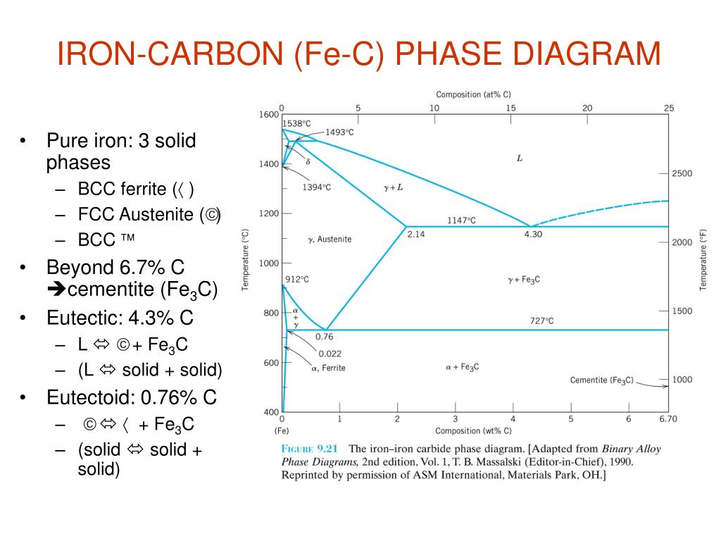
Engineering; Chemical Engineering; Chemical Engineering questions and answers; Consider the following Fe-C phase diagram: 1600 1538°C 1493°C L 1400 1394°C Y+L 1200 1147°C 2.14 4.30 7. The Iron-Carbon Diagram: A map of the temperature at which different phase changes occur on very slow heating and cooling in relation to Carbon, is called Iron- Carbon Diagram. Iron- Carbon diagram shows - the type of alloys formed under very slow cooling, proper heat-treatment temperature and how the properties of steels and cast irons
A study of the microstructure of all steels usually starts with the metastable iron-carbon (Fe-C) binary phase diagram (Figure 1). It provides an invaluable foundation on which to build knowledge of both carbon steels and alloy steels, as well as a number of various heat treatments they are usually subjected to (hardening, annealing, etc).

Fe-c phase diagram
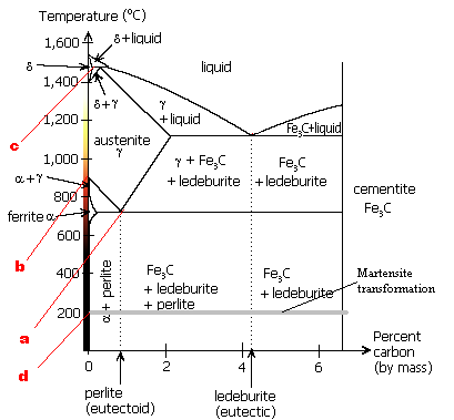
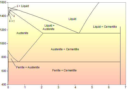
Nov 18, 2013 · • The Fe-C phase diagram is a fairly complex one, but we will only consider the steel and cast iron part of the diagram, up to 6.67% Carbon. 3. Fe – C Equilibrium Diagram 4. ©2003 Brooks/Cole, a division of Thomson Learning, Inc. Thomson Learning ™ is a trademark used herein under license. Figure 12.33 The iron-carbon phase diagram ... The diagram is not to scale, and the o-ferrite and 6-ferrite phase fields have been expanded for clarity 1600 .S+L Liquid (0) 1400 5+ Lty 1200 - ylousterite) Temperaturo/" 1000 + FeC 800 a + Fec Stools 600 Cast Irons Wire Geon Sows Nolls Rpilis Blades 400 1 2 Composition/wt% Figure 4.17 The iron-carbon existence diagram showing the approximate ... Mar 10, 2020 · Types of Ferrous Alloys on the Phase Diagram. The weight percentage scale on the X-axis of the iron carbon phase diagram goes from 0% up to 6.67% Carbon. Up to a maximum carbon content of 0.008% weight of Carbon, the metal is simply called iron or pure iron. It exists in the α-ferrite form at room temperature.
Fe-c phase diagram. T-T-T Diagram Figure 5-7 Isothermal transformation diagram (T-T-T diagram) for eutectoid composition steel. Structures resulting from transformation at various temperatures are shown as insets. (Courtesy of United States Steel Corp., Pittsburgh, PA.) Phases in Fe–Fe 3 C Phase Diagram ¾α‐ferrite‐solid solution of C in BCC Fe •Stable form of iron at room temperature. • Transforms to FCC g‐austenite at 912 °C ¾γ‐austenite‐solid solution of C in FCC Fe • Transforms to BCC δ‐ferrite at 1395 °C About Press Copyright Contact us Creators Advertise Developers Terms Privacy Policy & Safety How YouTube works Test new features Press Copyright Contact us Creators ... Mar 11, 2013 · Fe-C phase diagram is also used as the basis for the understanding of the heat treatment processes. Many of the basic features of Fe-C system influence the behaviour of even the most complex alloy iron and steels. For example, the phases found in the simple binary Fe-C system persist in complex steels, but it is necessary to examine the effects ...
2.3.5.5.3 Fe–C–S System. Ohtani and Nishizawa calculated the Fe–C–S ternary phase diagram on the basis of the thermodynamic analysis of Fe–C and Fe–S and Fe–C–S ternary melts [203]. The Gibbs free energy of individual phases was approximated by the interstitial solution model, assuming both C and S to be interstitial atoms. The simplest phase diagrams are pressure–temperature diagrams of a single simple substance, such as water.The axes correspond to the pressure and temperature.The phase diagram shows, in pressure–temperature space, the lines of equilibrium or phase boundaries between the three phases of solid, liquid, and gas.. The curves on the phase diagram show the points where the free energy (and … Fe-C Diagram . Fe-Carbon Diagram δ-ferrite –Solid solution of carbon in iron. Maximum concentration of carbon in δ- ... phase and δ-ferrite perform peritectic transformation, resulting in formation of austenite. Alloys, containing carbon more than 0.51%, but less than 2.06%, form primary austenite 1955. A review in [Metals], with the Fe-C phase diagram based primarily on [72Chi], has been sewing as one of the standard Fe- C phase diagrams until now. However, [79Agr] and [84Oht] pointed out errors in the thermodynamic model of [72Chi]. [82Kub] accepted phase diagrams derived thermodynamically by
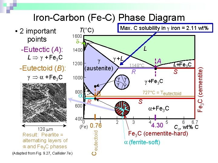
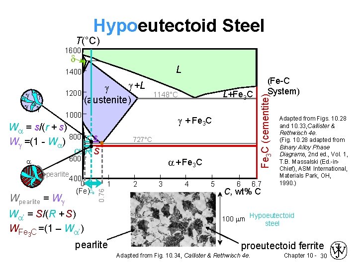
Mar 06, 2016 · The Fe-C phase diagram provides temperature-composition map of where the two phases (austenite and ferrite) occur. It also indicates where mixtures of these two phases can be expected. The Fe- C phase diagram is shown in Fig 2. In pure iron, austenite transforms to ferrite on cooling to 912 deg C. Fe-C phase diagram Review Fe-C phase diagram • 2 important points-Eutectoid (B): γ⇒α+Fe 3C-Eutectic (A): L ⇒γ+Fe 3C Fe 3 C (cementite) 1600 1400 1200 1000 800 600 400 0 12 3 4 5 66.7 L γ (austenite) γ+L γ+Fe 3C α+Fe 3C α + γ L+Fe 3C δ (Fe) C o, wt% C 1148°C T(°C) α 727°C = Teutectoid A R S 4.30 Result: Pearlite = alternating layers of αand Fe ... A critical review of published data provides a fairly accurate knowledge of the thermodynamic properties of all of the phases of the system Fe-C that are stable or metastable at atmospheric pressure. Selected data are shown as tables and equations. A proposed phase diagram differs only slightly from others recently published but has the following features. Peritectic compositions and the α-γ ...
A Thermodynamic Model For Non Stoichiometric Cementite The Fe C Phase Diagram Sciencedirect
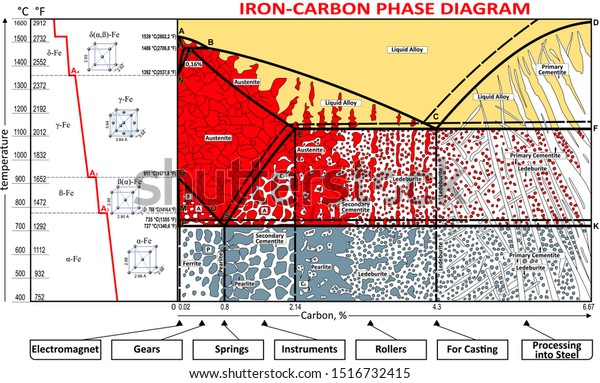
Mar 10, 2020 · Types of Ferrous Alloys on the Phase Diagram. The weight percentage scale on the X-axis of the iron carbon phase diagram goes from 0% up to 6.67% Carbon. Up to a maximum carbon content of 0.008% weight of Carbon, the metal is simply called iron or pure iron. It exists in the α-ferrite form at room temperature.
1
The diagram is not to scale, and the o-ferrite and 6-ferrite phase fields have been expanded for clarity 1600 .S+L Liquid (0) 1400 5+ Lty 1200 - ylousterite) Temperaturo/" 1000 + FeC 800 a + Fec Stools 600 Cast Irons Wire Geon Sows Nolls Rpilis Blades 400 1 2 Composition/wt% Figure 4.17 The iron-carbon existence diagram showing the approximate ...

Iron Carbon Phase Diagram Value Creation From Uzbekistan
Nov 18, 2013 · • The Fe-C phase diagram is a fairly complex one, but we will only consider the steel and cast iron part of the diagram, up to 6.67% Carbon. 3. Fe – C Equilibrium Diagram 4. ©2003 Brooks/Cole, a division of Thomson Learning, Inc. Thomson Learning ™ is a trademark used herein under license. Figure 12.33 The iron-carbon phase diagram ...
Dmitry Chernov Wikiwand
Phase Equilibrium Part 6 Chemistry Engineering Department 23102013
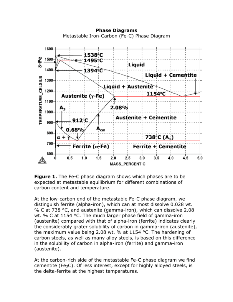
Phase Diagrams

Iron Carbon Phase Diagram Cementite Iron Angle Electronics Png Pngegg
Uobabylon Edu Iq

The Iron Carbide Fe Fe3c Phase Diagram Uprm Pages 51 67 Flip Pdf Download Fliphtml5

Doc 20160928 Wa0008 Pdf The Iron U2013iron Carbide Fe U2013fe3c Phase Diagram U2022 In Their Simplest Form Steels Are Alloys Of Iron Fe And Carbon C U2022 The Course Hero

Solved Looking At The Iron Carbon Phase Diagram Below Answer The 1 Answer Transtutors

Solved By Using The Iron Carbon Fe C Phase Diagram Chegg Com
Gotrawama Eu

Applications Of Fe C Phase Diagram T T T Diagram Figure 5 7 Isothermal Transformation Diagram T T T
Determination Of Microstructure And Phase Fractions In Steels Tec Science

Portion Of Fe C Equilibrium Phase Diagram 5 Download Scientific Diagram
Chapter 10 Phase Diagrams Issues To Address When

The Phase Diagram For The Iron Carbon Fe C System Is Shown Below Use It To Answer The Homeworklib

Lron Iron Carbide System Fe And Fe3c Iron Carbide Are The Components In The Fe Fe3c Phase Diagram It Is Also Possible To Have A Phase Diagram With Fe And C Graphite As The Components

Metastable Iron Carbon Fe C Phase Diagram
Gotrawama Eu
Iron Carbide Ispatguru

The Iron Carbon Alloys And Fe C Phase Diagram Mechanicalbase
Phase Diagram For Fe C X

Phase Diagrams
Vektor Stok Coloring Vector Ironcarbon Phase Diagram Tanpa Royalti 1516732415

The Iron Carbide Fe Fe3c Phase Diagram 2008 01 11nose Of The Ttt Curve The Diffusion Rates Are Greatly Reduced Under Such Conditions Is Not Possible To Form Pearlite And A Different

Solved By Using The Iron Carbon Fe C Phase Diagram Chegg Com

Iron Carbon Phase Diagram Google Search Metal Working Tools Metal Working Mechanical Engineering

Teach Yourself Phase Diagrams

Gate Metallurgical Engineering Iron Iron Carbide Phase Diagram

Iron Carbon Fe C Diagram First Phase Diagram Of Any Alloy To Be Download Scientific Diagram
Iron Phase Diagram Roy Mech
Ppt Phase Diagrams Powerpoint Presentation Free Download Id 4651426

Fe C Phase Diagram Iron Carbon Phase Diagram Explanation How To Make Iron Carbon Diagram Youtube
1
Dari Berbagai Sumber Steels An Introduction To Heat Treatment

Fe C Diagram Pdf Heat Treating Steel

The Iron Carbon Phase Diagram

Ppt Casts Irons Powerpoint Presentation Free Download Id 5686440
0 Response to "40 fe-c phase diagram"
Post a Comment