35 fe cr phase diagram
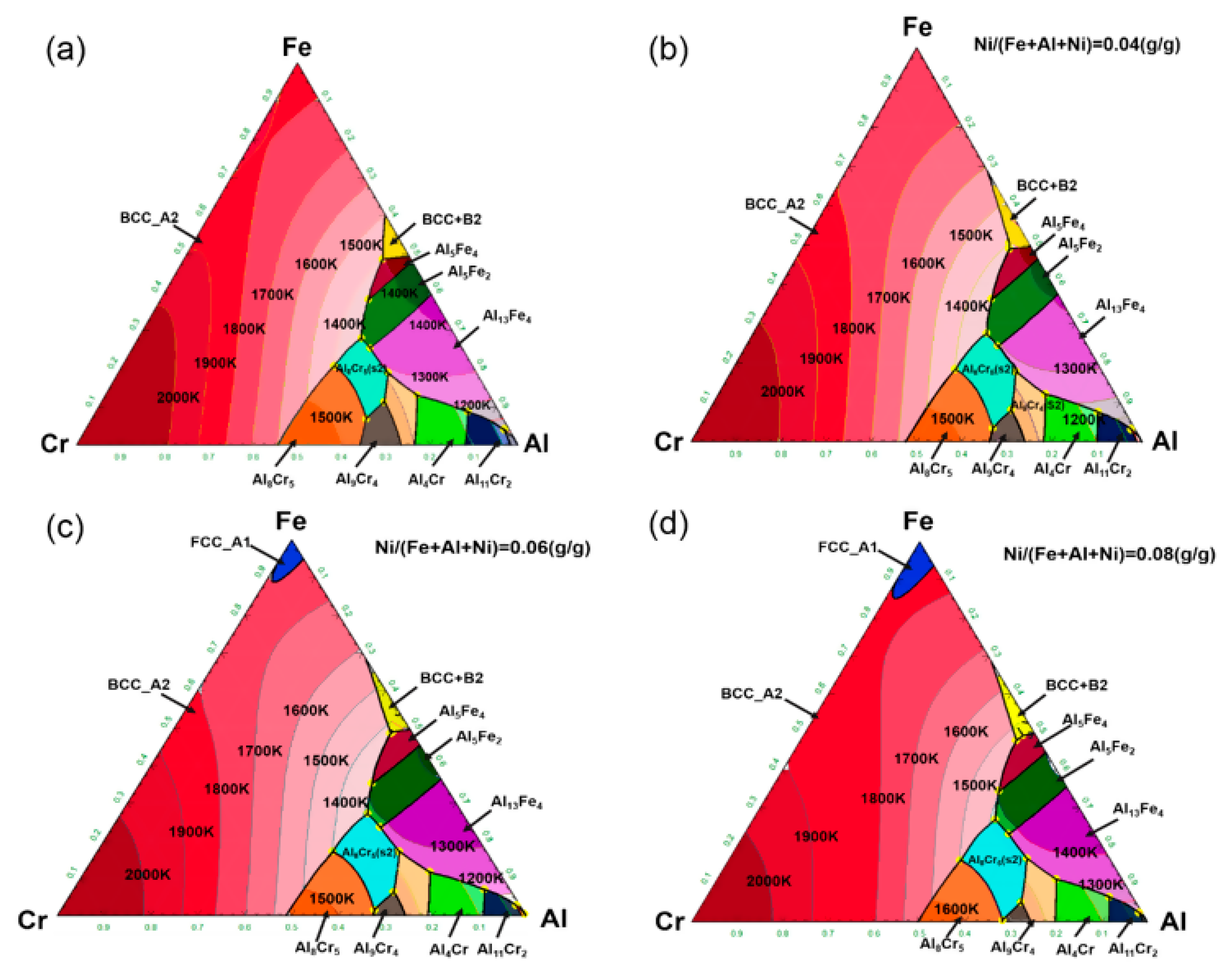
the phase diagram calculations of Fe-Cr-Al alloy, the irregular tetra-hedron (IT) cluster approximation [41] which is commonly used in literature [39,40,60] is adopted. Fig. 1 is the IT cluster and the four vertices of an IT cluster are labeled by i,,,jkl for convenience. The
The Fe-Cr system is re-assessed, focusing on an improved modeling of σ phase. The three sublattice model (Cr,Fe) 10 (Cr,Fe) 4 (Cr,Fe) 16 is parameterized to model the σ phase, solving discrepancies between computed and experimental site fractions of previous descriptions. Taking into account relative metastability trends of end-member compounds from first-principles analysis, only two ...
@article{osti_7218909, title = {Phase diagram of Fe--Cr--Co permanent magnet system}, author = {Kaneko, H and Homma, M and Nakamura, K and Ikada, M and Thomas, G}, abstractNote = {The miscibility gap of the ..cap alpha.. phase in Fe-Cr-Co permanent magnet alloys is constructed using mechanical hardness and Curie temperature measurements. . It is found that the miscibility gap of the Fe-Cr ...

Fe cr phase diagram
Transmission electron microscopy and the corresponding selected-area electron diffraction patterns of Fe-(10;20;30;40;47) wt. pct. Cr alloys heat treated isothermally from 500°C up to 1500°C at 100°C was employed to construct the equilibrium Fe-rich portion of the Fe-Cr phase diagram. It has been found to be quite different from the generally accepted one. Two regions of phase separation ...
3) Isothermal phase diagram of Fe-Cr-O system at 1 600°C was established. The relationshp between the chromium content of Fe-Cr melt and the oxide phase equilibrated was determined. below 1% Cr-cubic chromite, 1-7%Cr-c/a=1-0.95 above 7% Cr-Cr 2 O 3
The formation of σ phase was investigated in Fe-Cr-Ni-Mo alloys with high nitrogen content. The amounts of the σ phase are correlated with the calculated δ-Fe values. The Md-PHACOMP (Phase ...
Fe cr phase diagram.
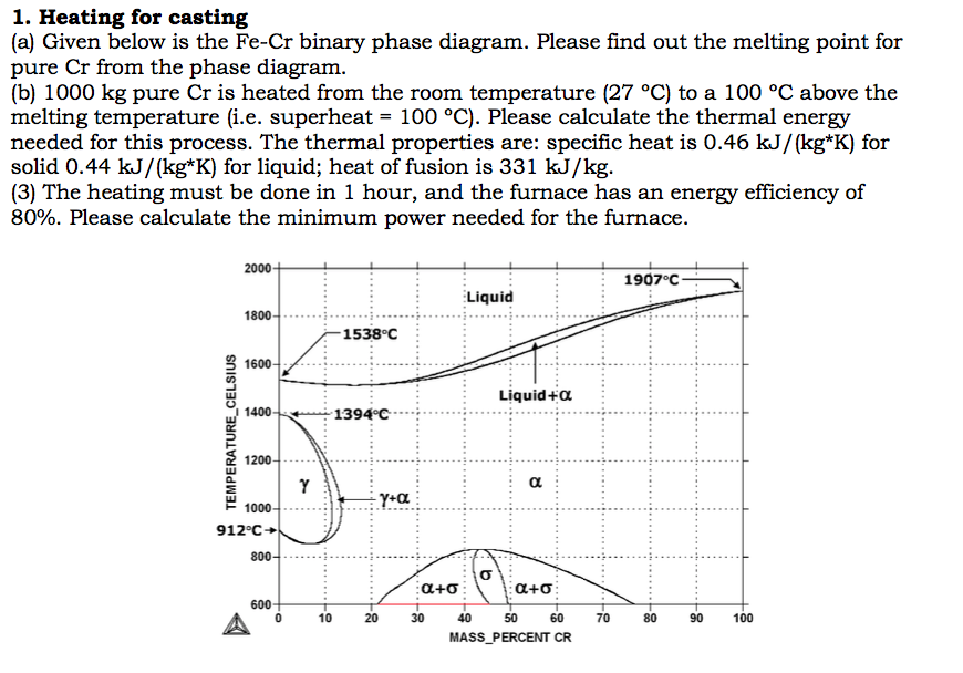
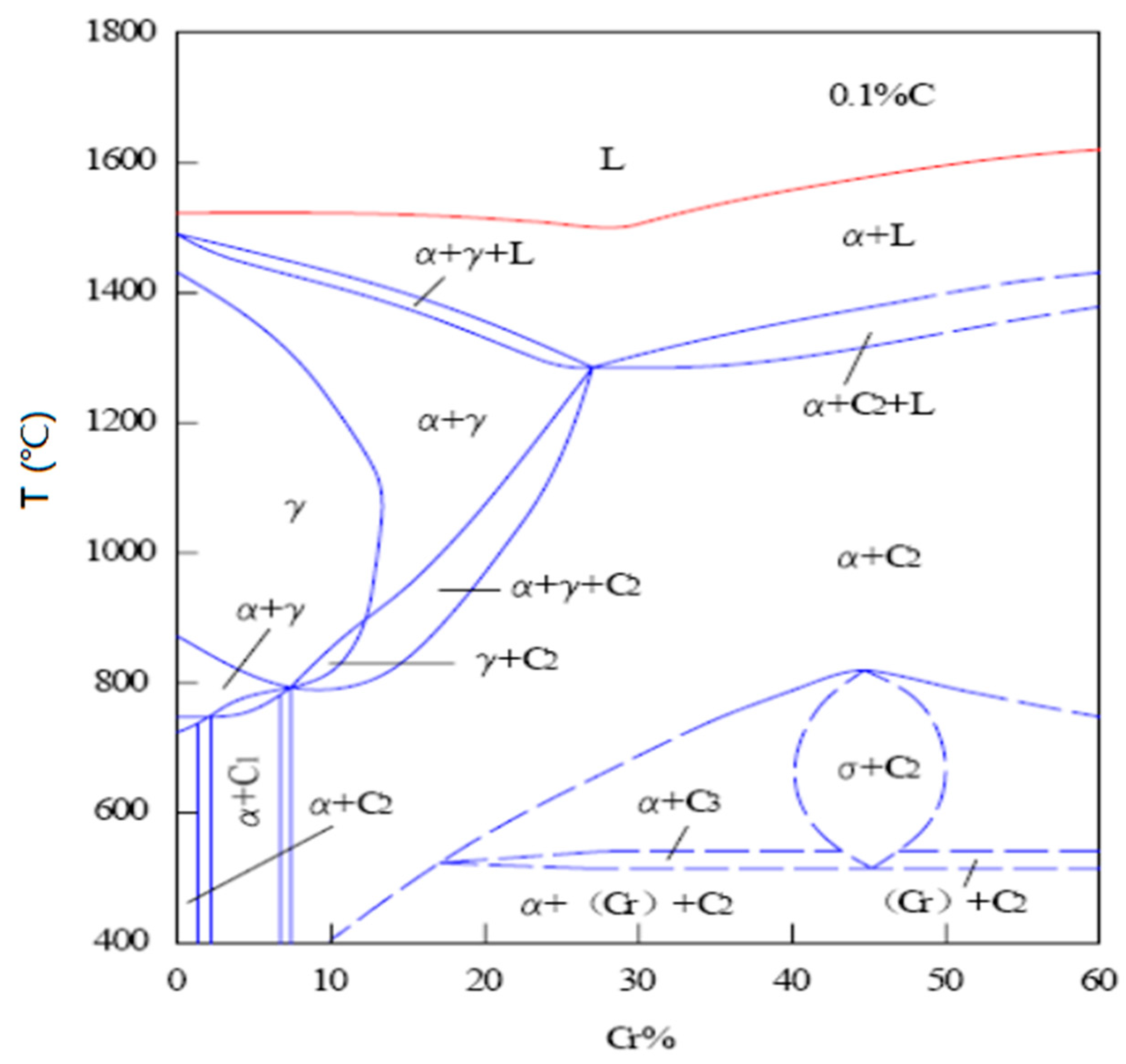
The phase diagram of the Fe-Cr binary system is at Fig 1. The melting point of Fe and Cr is taken at the pressure of 1 atmosphere as 1538 deg C and 1907 deg C respectively. The sigma phase, which is an intermetallic FeCr compound, can sometimes form in Fe-Cr alloys, such as AISI 316 or AISI 310 stainless steels.
The Ti 10 Cr 18 Fe 18 Co 27 Ni 27 and the Ti 16.7 Cr 16.7 Fe 16.7 Co 25 Ni 25 alloys exhibit (Ni, Co) 3 Ti precipitates embedded in an fcc matrix . The TiV x Cr y ZrNb system can contain a bcc phase with submicrometric precipitates or three bcc phases or a bcc phase and Laves phase, depending on the composition [12] .
-4-)Two-component or Binary phase diagrams: Temperature-composition diagram, P constant Composition (concentration): Mole or mass fraction (or percent) of a constituent i in a given alloy - Liquidus: the line above which the alloy is properly in a liquid (L) state -Solidus: the line below which the alloy is properly in a solid (α) state-Solvus: the line which represents the limit of solid ...
the ternary phase diagram with respect to the aus-tenite stabilized region in the low Cr composition has not beenentirely identified evenin the recent st.udy. Thepurpose of this study is to investigate the eq,ui-librium phasediagram of Fe-Cr-Mnsystem at 923 K (650'C), in particular, to examine the extent of a single phase reg_ion in the low Cr ...

![Binary iron-chromium equilibrium phase diagram [15], [18 ...](https://www.researchgate.net/profile/Mohammad-Alam-63/publication/315655489/figure/fig2/AS:535998077849606@1504803308716/Binary-iron-chromium-equilibrium-phase-diagram-15-18.png)








0 Response to "35 fe cr phase diagram"
Post a Comment