35 request to exit wiring diagram
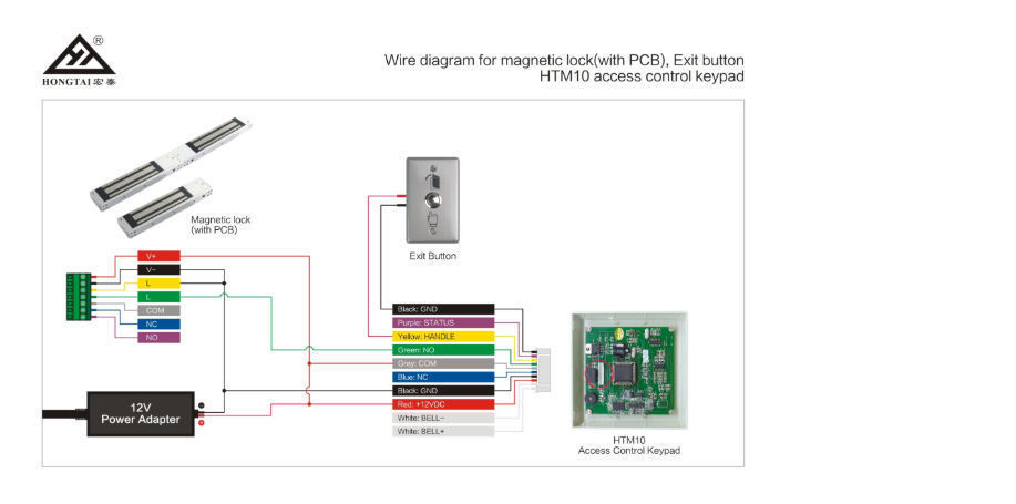
55- Signal Switch (Request to EXIT) The signal switch monitors the touch bar. Touch bar monitoring may be used to detect egress, sound an alarm, send a signal to a remote location, or de-energize an electromagnetic lock. Ordered as 55 Prefix. FEATURES. - WIRING INSTRUCTIONS— Magnetic lock or fail safe strike with button, keypad, maintained button and remote receiver. wired in series Power Supply for fail safe strikes and magnetic locks should be DC. If this is not available you may use an AC power source and wire inline a "Full Wave Bridge" rectifier. This will conver t the AC to DC.
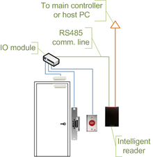
Request To Exit PIR sensors Installation Instructions 1.0 Description The DS160 is a Passive Infrared Detector (PIR) which is UL Listed as an Access Control Device under the UL 294 Standard. It is designed for "Request To Exit" (REX) interior applications.

Request to exit wiring diagram
Request To Exit PIR sensors Installation Instructions 1.0 Description The DS160/161 is a passive-infrared (PIR) detector designed for request to exit (REX) interior applications. ... the wiring through the trim plate and into the base before mounting the base and trim plate onto a single gang electrical box. Option RX (Request to Exit), LX (Latchbolt Monitor), DPS (Door Position Sensor, available non-deadbolt models), DM (Deadbolt Monitor, available deadbolt models). See pricebook for additional lock options. Note: Messaging indicators are not available for the L909x Series L Series mortise indicators Function + cylinder Trim Finish Handing Option code How to connect a Request to Exit button in a Kisi stand-alone setup. When installing Kisi as a stand alone product on a Fail-Safe lock, it is important to understand how to wire necessary, non-Kisi components to the setup. This guide specifically will explain the wiring of a Request to Exit (REX) button.
Request to exit wiring diagram. Instructions for wiring a VP1 reader-controller with a Request-to-Exit device. Instructions for wiring a VP1 reader-controller with a Request-to-Exit device. About Press Copyright Contact us Creators Advertise Developers Terms Privacy Policy & Safety How YouTube works Test new features Press Copyright Contact us Creators ... The following common wiring diagrams are available: One Single Door with Panic Bar. Electric Latch Retraction, with Auto Operator ... riser diagrams falcon exit devices ... wiring diagram request form . Common Wiring diagrams . wiring diagram for QEL panics ... Product Features. Passive Infrared Request to Exit Device. Designed to reliably release magnetic locks. Automatically cuts power to the lock, allowing the individual to exit without even realizing that the door is secured. Request to Exit (REX) output. Easily adjustable beam pattern.
BEA has a complete line of request-to-exit (REX) products including sensors, locking devices, push buttons and keypads. Building codes often require two forms of exit devices on a door, such as a motion sensor and a push button, to ensure that occupants are safely able to exit a building. Our sensors help meet these codes. RX Request to Exit ELECTRICAL SPECIFICATIONS Note: SPDT mechanical switch Voltage Current 125 VAC 3 AMP 30 VDC 2 AMP REV 3 rev date: 08/28/2012 Wiring Diagram Yellow Wire: (common) Red Wire: (normally open) Grey Wire: (normally closed) Wire Gauge: #22 AWG INSTALLATION INSTRUCTIONS 1. Remove chassis cover from device. 2. ENFORCER Outdoor Piezoelectric Request to Exit Pushbutton -LARM U.S.A., Inc 3SECO Wiring the Manual Override: SD-6176-SSVQ and SD-6276-SSVQ Only Connect the manual override button with the included wires. Notes a. Remove the thin panel on the bottom of the plastic cover to allow wiring to pass through. b. RCR-REX Request-to-Exit Dual Technology Motion Sensor Installation Instructions 2 Wiring This section provides examples of different wiring options. The options are all shown in the fail safe mode. Basic hook-up Figure 4 shows the basic hook-up for the RCR-REX, a power supply and a magnetic lock. When the sensor sees motion, power
These instructions cover installing and wiring remote options to the AL- 80 Series Alarmed Exit Device using the 546 wiring harness. Refer to instruction A7224B for additional instructions. Remote options include Remote Power, Remote Monitor, Request to Exit (REX), Door Status and Remote Reset. In addition, there are field selectable options: T.REX-LT-NL T.Rex request-to-exit detector with tamper and timer, white (unbranded) TREX-LT2 T.Rex request-to-exit detector with tamper, timer and 2 relays, white T.REX-LT2-NL T.Rex request-to-exit detector with tamper, timer and 2 relays, white (unbranded) T.REX-XL T.Rex request-to-exit detector with tamper, piezoelectric buzzer and timer, white LocksOnline Wiring Diagram 004. Oct 30, · Request to Exit Wiring Diagram ds ds installation guide high performance request to 3 3 8 disabling the request to exit the ds can be disabled by using terminal r and an external device such as an access control or burglar alarm system. Push Buttons. positive input wire of a magnetic lock. Note that another switching device such as a motion detector can be put between the white wire and the source of +V (as is shown in Figure 1). Figure 2 shows the internal schematic of the push button contacts and timer which helps clarify the unusual wiring method needed to maintain double break safety.
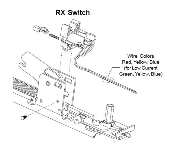
The L-Series switched to a handed modular three-wire request to exit (RX) switch.This change was originally completed on electrified locks in October 2014. The RX switch will have a molex connector attached re quiring use of Allegion Connect Harnesses and IVES hinges, or connector can be snipped off and traditional splicing methods employed to wire lock.

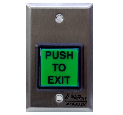
915Mhz. Wireless Door Control System. 2" Sq. LED Illuminated Exit Switch, w/ timer. Camden's CM-RQE70 PIR 'REQUEST TO EXIT' Detectors provide the latest word in design, with a complete list of "high performance" features, including secondary activation device input, door monitoring, two relay outputs, and tamper alarm.

The TS-2 request to exit station, with square push button, provides a convenient way to add authorized access control to a variety of applications. Features. Standard Features. Switch mounted on single gang wall plate with 430 stainless steel finish;

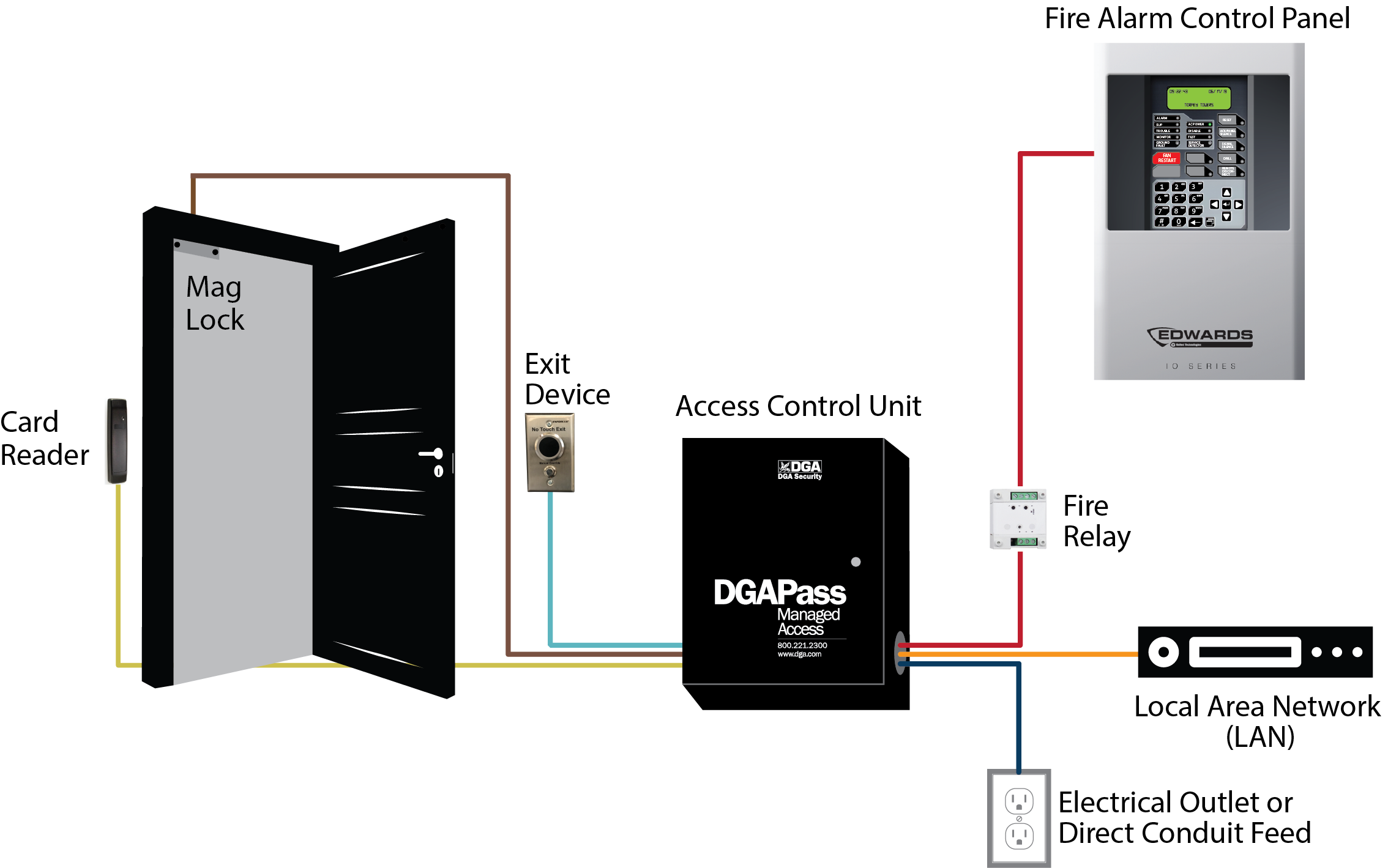
Wiring. The basic hook-up consists of the REX (Request to Exit) device, a power supply, and a maglock. When the REX sees motion, power is removed from the maglock.

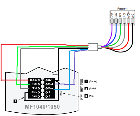
Wire sizes recommended for Wiegand interface (4-conductor) are as follows: Distance Size Up to 200 ft 22 gauge Up to 300 ft 20 gauge Up to 500 ft 18 gauge 1. Below is the standard wiring for most HID proximity card readers and keypads. 2. Find the specific wiring configuration for your Wiegand reader or keypad in the documents that came
Wiring diagram The diagram below shows how to wire 8KW and 9KW electri˜ed locks. Figure 1—Wiring diagram for 8KW and 9KW electri˜ed locks (9KW with RQE shown) Run wires through the door or mount wires to the door sur-face with wire molding. To ˜nd the correct wire gauge for wire runs, see Figure 2 on the reverse side. RQE (Request-to-exit ...

DS160/DS161 Installation Guide High Performance Request-to-Exit Sensors 1.0 Description The DS160/161 is a passive-infrared (PIR) detector designed for Request to Exit (REX) interior applications. The DS160/161 is UL Listed as an access control device under the UL 294 Standard and is listed for Class I for UL Canada under ULC-S319

Wiring Diagram: Installation: 1. Run four wires through the wall to a single-gang or slimline back-box. 2. Connect the four wires from the back-box to the Request-to-Exit Sensor according the Wiring Diagram above. 3. Screw the plate into the back-box, taking care not to crimp the wires. 4. Remove clear protective film from the sensor before use.

DS150i/DS151i Installation Guide Request-to-Exit PIR Detectors 1.0 Description The DS150i is a passive-infrared detector designed for request to exit (REX) applications. It is UL Listed as an access control device under the UL 294 standard and is listed for Class I for UL Canada (ULC-S319). For
THIS WIRE DIAGRAM, BE SURE ALL PRODUCTS ARE VOLTAGE COMPATIBLE. ... Activating the Request-to-Exit (REX) motion sensor will unlock the magnetic lock ...1 page
Connect the 4 wires to the Request-to-Exit Sensor according to the Wiring Diagram above. 3. Reattach the Stainless Faceplate to the enclosure taking care not to ...8 pages
56- Electric Latch Retraction Exit Devices Installation and Wiring Instructions With Optional 53- Latchbolt; 55- Request to Exit; and TL- (SARGuide) Connection Instructions FOR INSTALLATION ASSISTANCE CONTACT SARGENT • 1-800-810-WIRE (9473) • www.sargentlock.com SECTION I: OVERVIEW 1. Description

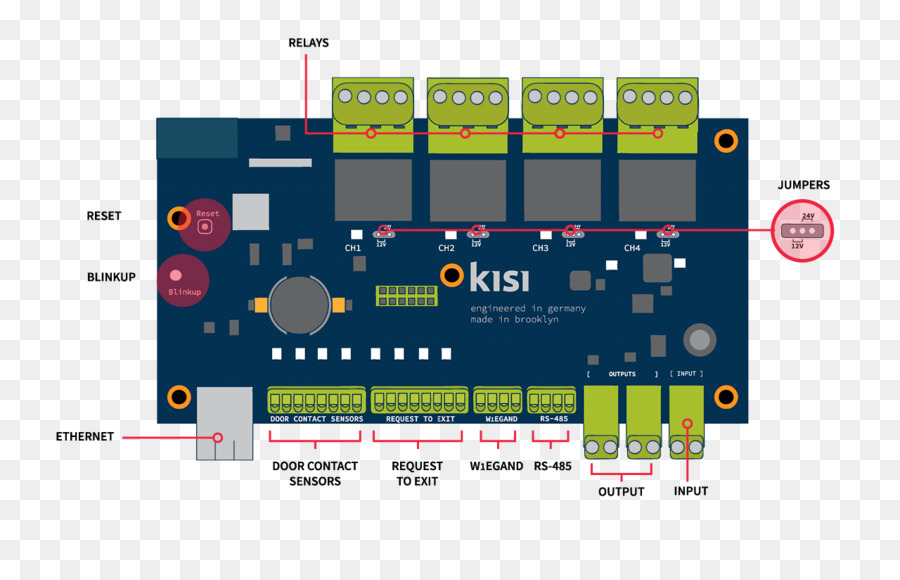
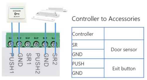
A crucial step in setting up your push-to-exit button is properly wiring all the components. In an IP system like Kisi, this will involve the door lock, the access reader, the controller, the power supply, and the push-to-exit button (as well as optional contact sensors). The following diagram outlines the setup with an electric strike lock.
for “Request To Exit” (REX) interior applications. ... control this type of application. ... to run your wiring through the trim plate and into the base.8 pages
How to connect a Request to Exit button in a Kisi stand-alone setup. When installing Kisi as a stand alone product on a Fail-Safe lock, it is important to understand how to wire necessary, non-Kisi components to the setup. This guide specifically will explain the wiring of a Request to Exit (REX) button.

Option RX (Request to Exit), LX (Latchbolt Monitor), DPS (Door Position Sensor, available non-deadbolt models), DM (Deadbolt Monitor, available deadbolt models). See pricebook for additional lock options. Note: Messaging indicators are not available for the L909x Series L Series mortise indicators Function + cylinder Trim Finish Handing Option code
Request To Exit PIR sensors Installation Instructions 1.0 Description The DS160/161 is a passive-infrared (PIR) detector designed for request to exit (REX) interior applications. ... the wiring through the trim plate and into the base before mounting the base and trim plate onto a single gang electrical box.


0 Response to "35 request to exit wiring diagram"
Post a Comment