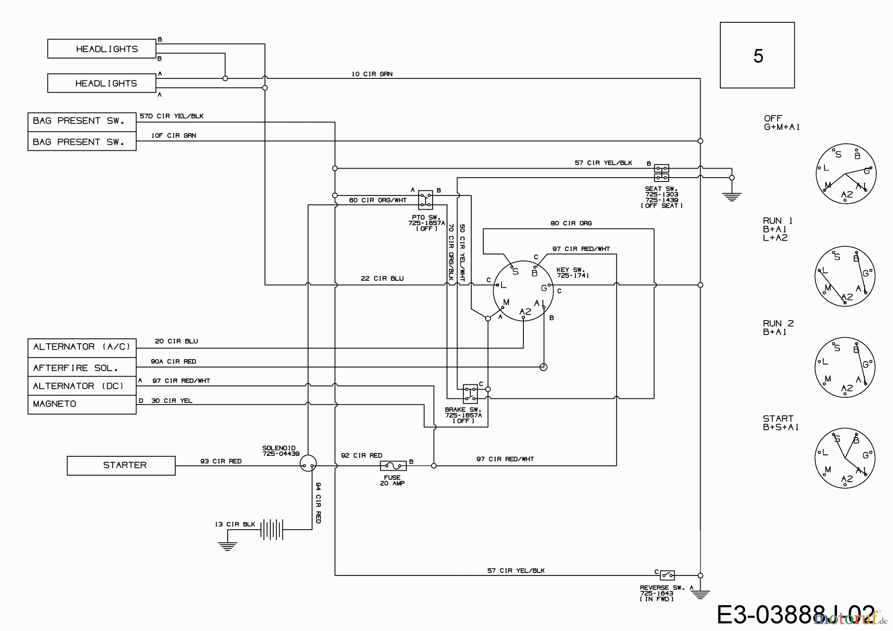
35 t92s7d22-22 wiring diagram
3Ø WIRING DIAGRAMS 1Ø WIRING DIAGRAMS Diagram ER9 M 3~ 1 5 9 3 7 11 Low Speed High Speed U1 V1 W1 W2 U2 V2 TK TK Thermal Overloads TWO SPEED STAR/DELTA MOTOR Switch M 3~ 0-10V 20V 415V AC 4-20mA Outp uts Diagram IC2 M 1~ 240V AC 0-10V Outp ut Diagram IC3 M 1~ 0-10V 4-20mA 240V AC Outp uts These diagrams are current at the time of publication ...
T92s7d22-22 Wiring Diagram; Wiring Diagram For 220 Volt Baseboard Heater; Dt466 Idm Wiring; Intertherm E2eb Cooling Fan Relay Wiring Diagram; Ge Window Ac Wiring Diagram Aez05lvq2; Lq4 Wiring Harness; Rb20det Wiring Diagram; Traxxas T Maxx 3.3 Parts Diagram; John Deere 1070 Parts Diagram; Kenmore Sewing Machine Tension Assembly Diagram
Wiring Diagram For Directv Swm; Everstar Mpk-10cr-1 Wiring Diagram; Ansul R 102 Wiring Diagram; 2003 2005 Gmc Delphi Radio Wiring Diagram With Steering Wheel Control; 1994 Plymouth Acclaim Fuel Gauge Wiring Diagram; Sears Model #917.275970 Tractor Wiring Diagram; 300w Power Supply Model Dps-300pb-3a Wiring Diagram; Siemens Dact Wiring Diagram

T92s7d22-22 wiring diagram
T92S7D22-22 - Carrier OEM Replacement Furnace Relay by Carrier. 4.4 out of 5 stars ...
T92s7d22-22 Wiring Diagram. T92S7D - Carrier OEM Replacement Furnace Relay by Carrier: I've double checked the wiring diagram on the unit to make sure it's hooked up correctly. Alternate Search Terms: T92S7D Datasheet T92S7D Component T92S7D Integrated Circuit T92S7D Schematic T92S7D Expected Electrical Life: , operations at rated load.
MOUNTING When a number Original PDF 08-Apr-05 curve sheet 2222 050 17103 2222 052 58221 ELECTROLYTIC CASE d 2222 102 56332 050 17103 050 PED-PW
T92s7d22-22 wiring diagram.
2018 Common Connection Diagrams 7 2.5 Wire and ring terminal specifications 2.5.1 BG or BGE When connecting the supply power from the motor terminal block to the brake rectifier, follow the specifications below. Connecting wire should be AWG14, MTW, 600V, 105°C temperature rating and black color.
Wiring diagrams, sometimes called "main" or "construc-tion" diagrams, show the actual connection points for the wires to the components and terminals of the controller. They show the relative location of the components. They can be used as a guide when wiring the controller. Figure 1 is a typical wiring diagram for a three-phase mag-
7-184949-22 Wiring Diagram With Capacitor; T92s7d22-22 Wiring Diagram; Wfco Wf-8712 Wiring Diagram; Husqvarna Yth1542xp Wiring Diagram; Pixhawk Mini Osd Module Wiring Diagram; 1977 Datsun 280z Fuel Pump Relay Wiring Diagram; Wiring Diagram For Mobility Svm Lift System; Wiring Diagram Wd-862; Crosley Dryer Wiring Diagram; Recent Comments ...
Even a small boat (3-5 loads) we'd recommend at least 12AWG wire for this. 10AWG for larger boats (5-10 loads) is normal. 8AWG is getting toward over-kill in most cases for boats under 30ft. Remember these are all generalities, there are many valid reasons to make exceptions.
A-premium E3566m Fuel Pump Wiring Diagram; T92s7d22-22 Wiring Diagram; Mir-fdsd99s-g2-pw-sm-set Wiring Diagram; Traeger Parts Diagram; Pixhawk Wiring Diagram; 2001 Nissan Pathfinder Bose Pn-2439n18 Pin Wiring Diagram; Millermatic 35 Parts Diagram; Comfort System Grundfos Wiring Diagram; 1966 Vw 1300 Wiring Diagram Fuse Box; Svp Sa 400 Wiring ...
T92S7D22-22-01 - Carrier OEM Replacement Furnace Relay. 2 offers from $32.99. Next page. ... I've double checked the wiring diagram on the unit to make sure it's hooked up correctly. Seems just like it fails after a couple years on it's own without even being engaged. 1-star, but no other choice since it the part my OEM used for their unit. ...
22 pin cable . 10 pin cable. Connector amplifier "JEEP GRANG CHEROKEE 1999 - 2004 Plug the amplifier. ... Car stereo wiring diagrams car radio wiring car radio wiring colors car radio wire car radio connections wiring diagram car radio wire colours. ...
3-Pole 3-Wire 125V/250VAC 3ø 250VAC 3ø 480VAC L8-20R L8-30R 480V AC G EQUIP. GR. L9-20R L9-30R 600V AC EQUIP. GR. G 2-Pole 3-Wire Grounding 480VAC 600VAC Wiring Devices - NEMA Wiring Diagrams wwwautomationdirectcom Wire Management tWCC-38 1-800-633-0405 For the latest prices please check AutomationDirectcom
always use wiring diagram supplied on motor nameplate. w2 cj2 ui vi wi w2 cj2 ui vi wi a cow voltage y high voltage z t4 til t12 10 til t4 t5 ali l2 t12 ti-blu t2-wht t3.org t4-yel t5-blk t6-gry t7-pnk t8-red t9-brk red tio-curry tii-grn t12-vlt z t4 til t12 tio til
If you are replacing or rebuilding parts of the small engine on your lawn mower, snow blower or other outdoor power equipment, the basic schematics or wiring diagrams of our alternator systems are available in our guides below: Engine/Alternator Replacement Guide. Ignition/Starter Diagram. 6-Pin Wire Harness Assembly Installation Guide.
Typical Wiring Diagram . the relay recognizes that a mat is wired to the input rather than a N.C. safety switch with a cross.Sep 28, · BMW Wiring Diagram. Truly, we have been noticed that Starter Wiring Diagram BMW X5 is being one of the most popular issue at this time.
22 individually fused circuits, conveniently bundled into 11 "quick start"bales. Each wire strand is color-coded and labeled every 6"for easy identification. Includes proven GM-type switches, for easy repair/replacement if needed. Complete wiring harness kit weighs less than 8 lbs. installed. Charts.
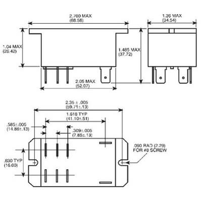
The T92S7D22-12 is a general-purpose High Power Relay with top sealed, not wash-tight, not tape sealed on bottom enclosure and 2-form-A (2 NO) AgSnO₂ contact. This T92-series features panel mount via flanged cover, QC terminal, non-latching coil and 12VDC coil voltage and designed to control compressor loads.
1) - Wiring Circuit Diagram (340817-101) ... 1) - Installation Instructions (482 01 2226 07) ... ICP 1170674 RELAY 22VDC DPST T92S7D22-22
Samcom 10 Channel Digital Fm Wireless Intercom System For Home And. Intercom System Door Bells Chimes Diagram Electrical Wires. 9d44 4 Wire Intercom Wiring Instruction Diagram Wiring Resources. Spa Afff Fire System Complete 4 Liter System 2 Pull Cables Fia18 L4s. Spa M1 V2 Zenitel.
The wiring diagrams are grouped into individual sections. If a component is most likely found in a par-ticular group, it will be shown complete (all wires, connectors, and pins) within that group. For exam-ple, the Auto Shutdown Relay is most likely to be
Z4-21 Z34 Bi-Energy Sepex - Ground Control Box Wiring Diagram Z4-22 Z34 Bi-Energy Sepex - Swing Chassis & Boom Wiring Diagram Z4-23 Z34 Bi-Energy Sepex - Drive Chassis Wiring Diagram Z4-24 Z34 Bi-Energy Sepex - Power Wiring Diagram Z4-25 Z34 Bi-Energy Sepex - Engine Wiring Diagram Z4-26 Z30N Z34N Z34DC - Hydraulic Schematic
Download FREE diagrams, schematics, service manuals, operating manuals and other useful information for a variety of products. Currently we have 27502 Diagrams, Schematics, Datasheets and Service Manuals from 978 manufacturers, totalling 16.22 GB and the range is expanding all the time.
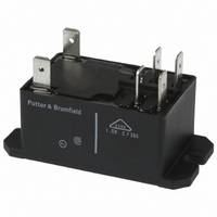
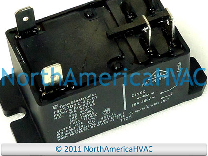
| Shortys Pumps Located Near Indianapolis, Indiana Potter & Brumfield Relay Model T92S7D22-22 [HN61PC003] - Potter & Brumfield relay model T92S7D22-22 Manufactured for Carrier Corp as P/N HN61PC002, HN61PC003 Coil rating 22 Volts Double pole single throw N.O. 30 A 277 VAC 20 A 28 VDC 1 HP 120 VAC 3 HP 240 VAC TV10 120 VAC OEM Carrier parts Shipping rate for continental USA
Order today, ships today. T92S7D22-22 - General Purpose Relay DPST-NO (2 Form A) 22VDC Coil Chassis Mount from TE Connectivity Potter & Brumfield Relays. Pricing and Availability on millions of electronic components from Digi-Key Electronics.
Relay Solutions. TE Connectivity's (TE) broad range of relays and contactors serve a variety of applications. The TE product line includes leading brands such as AGASTAT, AXICOM, CII, KILOVAC, OEG, P&B, PRODUCTS UNLIMITED, and SCHRACK. Switching capabilities range from dry circuit to 1600A, up to 70kV, and as high as 6GHz.
Wiring Diagrams. Please choose a year from the menu at left to start your search.
Wiring Diagram Pictures 06.09.2018 06.09.2018 2 Comments on Bissell Proheat 2x 9200 Hose Diagram How do I check the roller brush bearings on my Bissell Proheat Protech series? 1 answer · bissell proheat 2x ,,, View and Download Bissell ProHeat 2X Series service center manual online.
READ T92S7D22-22 Wiring Diagram Collection Read wiring diagrams from negative to positive in addition to redraw the routine as a straight range. All circuits usually are the same : voltage, ground, individual component, and buttons.
Forest River Wiring Diagram - forest river cardinal wiring diagram, forest river cherokee wiring diagram, forest river fr3 wiring diagram, Every electric arrangement consists of various diverse parts. Each part should be set and connected with different parts in specific manner. If not, the arrangement won't function as it ought to be.
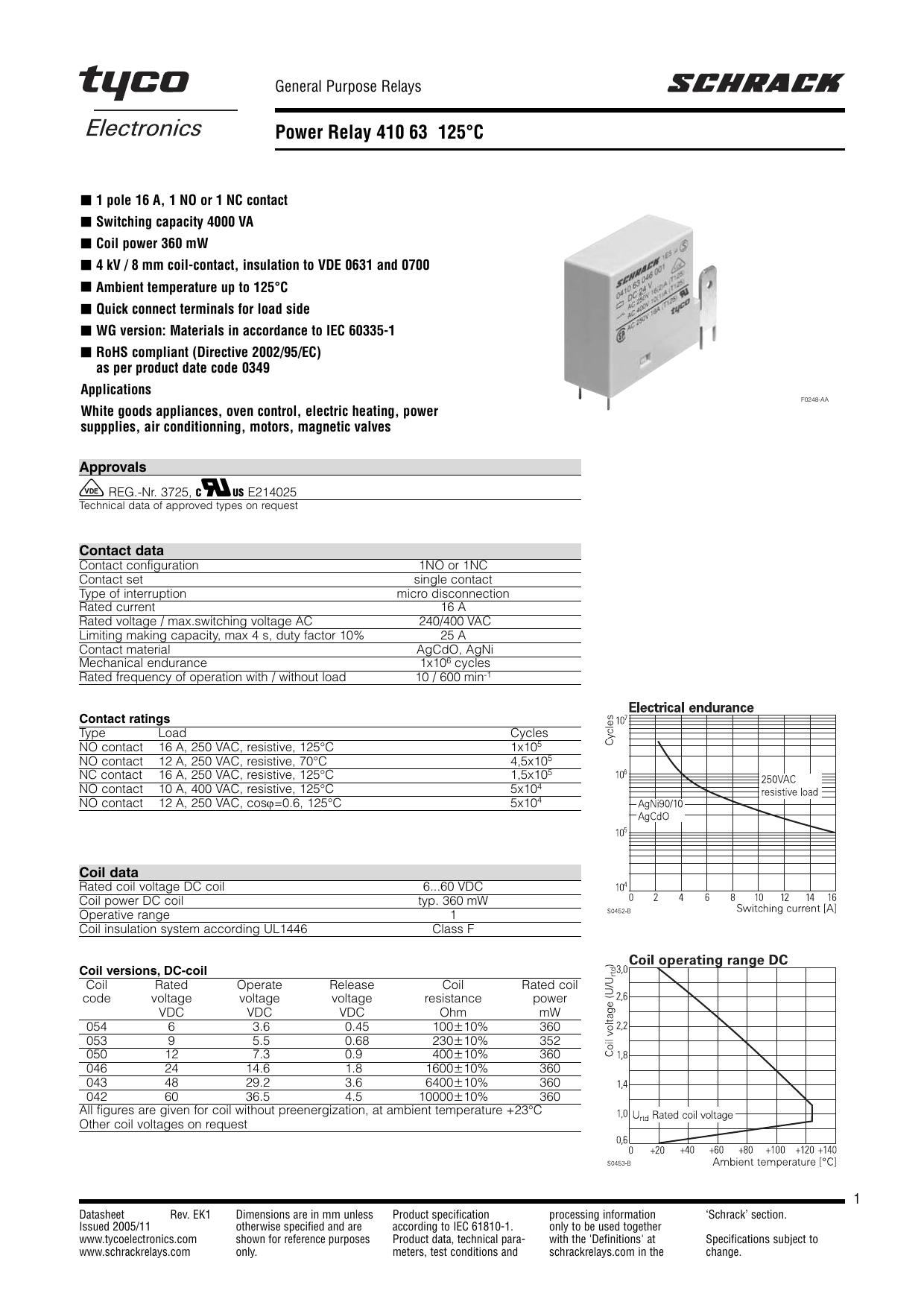
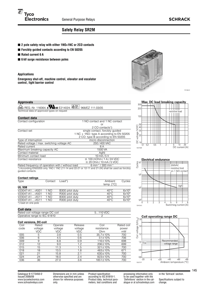
Request Tyco Electronics T92S7D22-22: T92S7D22-22=T92 online from Elcodis, view and download T92S7D22-22 pdf datasheet, More Switches & Relays specifications. Page 3.
![Carrier Fan Control Circuit Board HK61EA002 [HK61EA002] | Shortys Pumps Located Near Indianapolis, IndianaNationwide Armstrong Pump Distributor](https://www.shortyspumps.com/images/1/HK61EA002.jpg)
Carrier fan control circuit board hk61ea002 [hk61ea002] | shortys pumps located near indianapolis, indiananationwide armstrong pump distributor











0 Response to "35 t92s7d22-22 wiring diagram"
Post a Comment