37 ge electric motor wiring diagram
GE Appliance - How to Obtain a Wiring Diagram or Schematic tip products.geappliances.com. If you cannot locate the wiring diagram on your appliance, you can call the GE Appliances Answer Center to obtain one. You will need to have your complete model number. The diagram may be mailed or e-mailed. General Electric Motors Wiring Diagram - Gooddy, size: 800 x 600 px, source: gooddy.org. Below are several of the top illustrations we get from different sources, we wish these pictures will work to you, and hopefully really appropriate to just what you want regarding the General Electric Motor Wiring Diagram is.
MARATHON MOTORS (115VAC) (FORMERLY GENERAL ELECTRIC) 115VAC WIRING PROCEDURE FOR ¾ HP MARATHON MOTOR MODEL 5KC42JN0214 AND 1 HP MARATHON MODEL 5KC49PN0216. The following procedure is for wiring the pre-wired drum switch* to the motor using 14/5 control cable supplied by BH-USA. 1. MOTOR BLUE TO MOTOR TERMINAL 5 2. SWITCH GREEN TO GROUND 3.

Ge electric motor wiring diagram
A Repulsion Electric Motor is by definition a single phase motor which has a stator winding arranged for connection to the source of power and a rotor winding connected to a commutator. Brushes and commutators are short-circuited and are placed so that the magnetic axis of the rotor winding is inclined to the magnetic axis of the stator winding. Motor Test for Series Carts: Use a floor jack under the rear end center section to lift the rear wheels off the ground. Make sure you can turn the wheels by hand. Mark and remove all four motor wires. Use the below diagram and a fully charged 12 volt car battery. Make the jumper wires using 6 gauge battery cables. always use wiring diagram supplied on motor nameplate. w2 cj2 ui vi wi w2 cj2 ui vi wi a cow voltage y high voltage z t4 til t12 10 til t4 t5 ali l2 t12 ti-blu t2-wht t3.org t4-yel t5-blk t6-gry t7-pnk t8-red t9-brk red tio-curry tii-grn t12-vlt z t4 til t12 tio til
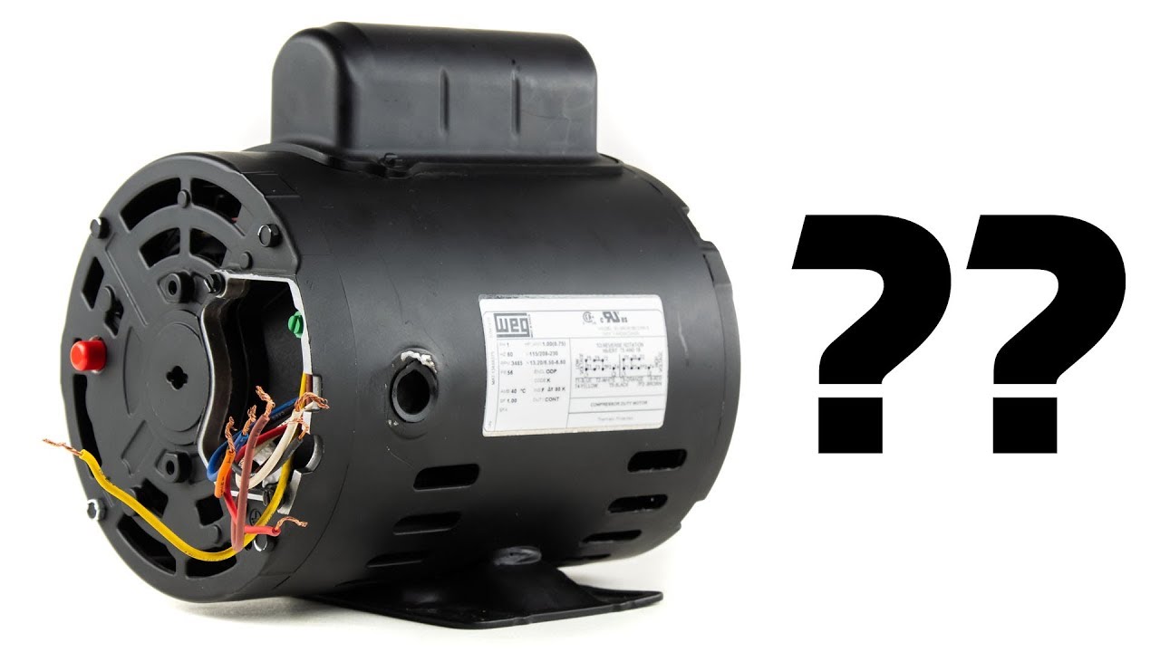
Ge electric motor wiring diagram. Ge Motor 5Kc Wiring Diagram from ww2.justanswer.com. Print the wiring diagram off in addition to use highlighters to trace the circuit. When you make use of your finger or the actual circuit together with your eyes, it's easy to mistrace the circuit. 1 trick that We use is to print exactly the same wiring picture off twice. Ge Dryer Wiring Diagram - ge clothes dryer wiring diagram, ge dryer motor wiring diagram, ge dryer timer wiring diagram, Every electric structure consists of various unique components. Each part ought to be placed and linked to different parts in particular way. If not, the arrangement won't work as it ought to be. Ge Motor Starter Wiring Diagram Sample. Variety of ge motor starter wiring diagram. A wiring diagram is a streamlined conventional photographic representation of an electric circuit. It reveals the components of the circuit as simplified forms, and the power and signal links between the gadgets. A wiring diagram normally offers information concerning the relative setting as… Wiring up a GE KC series motor. L stands for "line", and would represent terminals 1 and 6. This is what you connect your hot and neutral to from your feed. Terminals 2 & 4 and 3 & 5 represent your run windings. When 2 & 3 and 4 & 5 are jumpered, this means your run windings are connected in parallel and the motor is set up for low voltage.
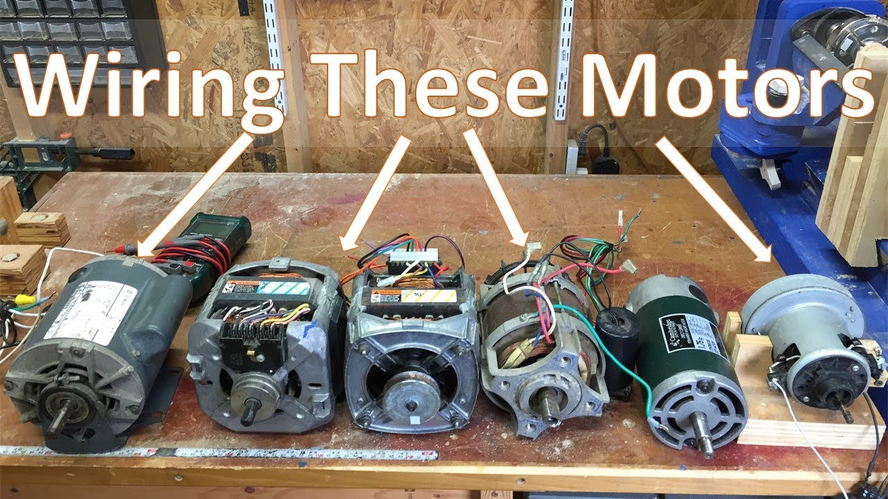
These diagrams are current at the time of publication, check the wiring diagram supplied with the motor. *NOTE: Refer to the motor manufacturer's data on the motor for wiring diagrams on standard frame Ex e, Ex d etc. motors. Inst Maint & Wiring_5.qxd 20/11/2015 11:37 AM Page 6 Dan T. RE: old GE single phase motor wiring diagram. Tmoose (Mechanical) (OP) 26 Jun 11 10:46. The 11 wires suggests its a 3 phase motor, based on a variety of dual voltage wiring info on the 'Net. However The link below mentions a 1.5 HP motor running on 110/220 (certainly single phase). The first first 6 characters in the model number (5KC184 ... ECM, GE Commercial Motors and GE Capacitors logos on all branded . with the components and wiring diagram, check for and follow any on board . Genteq introduced the Constant Torque motor (model X13) to the. GE ECM-driven systems. For ease of "Thermostat Wiring Diagrams", found in Square motor control. Unpainted, cast aluminum motor control. Ge electric motor wiring diagram. Ge tri clad capacitor motor model 5kc184ag201c 15hp 1725 rpm anyone know how to get the diagram. The motor is listed as. But if the manual cannot be found the job becomes tougher. I show how to wire several different types of motors and explain some of the important components. I will be using it along with the ...
HI, I have a GE motor on my table saw that was wired for 220vac. I want to change it back to 110vac. Problem is that the wiring plate is missing. Motor number is 5KC49TG1458X IT'S A 2HP motor Currently it has the following wires connected motor has 4 threaded studs marked 1-2-3-4- Power in is green to ground,white to #4 and black to #1 The motor wires are as follows Orange to #3 and Blue to #4 ... Ge Motor 5kc Compressor Duty Motor Wiring Diagram. The Electrical Apparatus Service Association, Inc. (EASA) is an Compressor Duty Motors - ODP Enclosure - Rigid Base - Single-Phase. Permanent Magnet. to print dimensional drawings and connection diagrams in PDF .. Marathon Electric Hazardous Duty Motor Temperature Code Chart .. Jul 02, 2019 · 3 phase motor wiring diagram 12 leads – What’s Wiring Diagram? A wiring diagram is a form of schematic which uses abstract pictorial symbols to exhibit each of the interconnections of components inside a system. Ge Motor P 567 S Mod 5kcp39kg Wiring Diagram. Back To GE Air-Conditioner Model: AGV10 GE Air Conditioner .. GE 5KCP39GG S S 1/3HP 4 Speed Furnace Blower Motor. Items 1 - 24 of GE Electric Motor 5KCP39KG Volt Single Phase. 30 A 1 PH 60 HZ Motor mount is attached to motor Replaces P/N B, .
electrical wiring diagrams for air conditioning systems. 3 wire and 4 wire condensing fan motor connection hvac school. i bought a 4 hp marathon electric pool pump with a high and. ge 1/3 hp ac electric motor 115/200230 vac 1625/1350 rpm ls56y frame a4p17nz38a. diagram wiring diagram general motors hei full version hd.

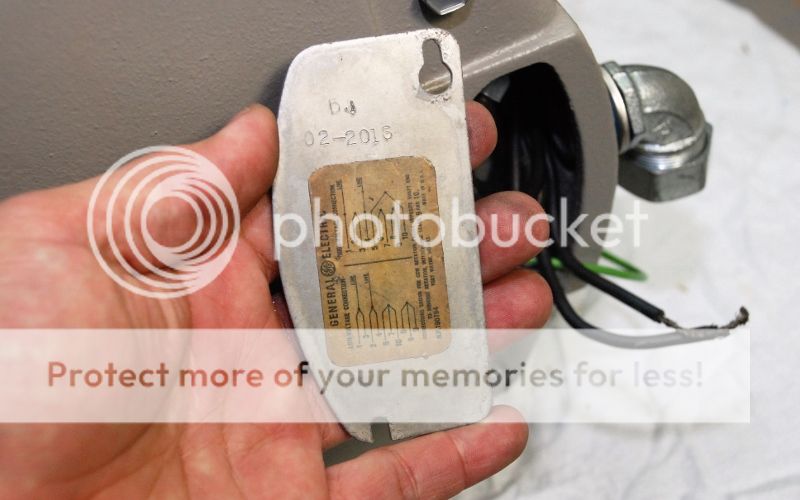
A.o. smith motor wiring general electric motor wiring dryer motor wiring Ge Motor Wiring Diagrams Electric Motor Wiring Ge Motor 5kc Wiring. Here is a picture of a G.E. Tri-clad motor terminal box cover with the wiring diagram for a 5KC model, 10 wire, /vac, 1 phase motor.
Ge Motor Wiring Diagram - Database. Repairing electrical wiring, a lot more than any other household project is about protection. Install an outlet correctly and it's as safe as that can be; do the installation improperly and it can potentially deadly. That's why there are numerous guidelines surrounding electrical cabling and installations.
Furthermore, the heat pump condenser fan motor will not. The wiring for the heat pump condenser fan motor will be slightly different. The black wire (noted in the wiring diagram) will likely be terminated on a control board. This control board is the defrost control board. It also controls the condenser fan motor in a heat pump.

Electric Motor Wire Marking & Connections. For specific Leeson Motor Connections go to their website and input the Leeson catalog # in the "review" box, you will find connection data, dimensions, name plate data, etc. www.leeson.com Single Phase Connections: (Three Phase--see below) Single Voltage:
I have an old GE motor that I would like to use at 115 volts. This motor is currently wired for 220 volts. The cover plate has the diagram listing the information but is unreadable. The current wiring configuration is as follows: Tied together are (2,3) (6,7) (5,9) and (8,10) Leads 1 and 4 are tied to line voltage. The motor information is as follows: General Electric Tri/Clad 2hp Model number ...
I bought an old air compressor that has a 1.5HP electric motor made by GE. It's an old motor, but it works fine. The motor is designed to run on either 120V or 240V AC. The problem is that this motor was ... wiring diagram for ge motor 5kc35k6335 please , need wiring diagram for above motor. thanks ...
When the motor starts, the electromagnet stops, and the "start" circuit stops. But the "run" circuit stays on, and the motor runs. Dishwashers have a relay starting switch mounted either beneath the tub or in the control console. You can usually figure out which terminals to test across by looking at the wiring diagram.

Practical Machinist Largest Manufacturing Technology Forum On The Web. 2 sd motor wiring need a purple wire doerr lr22132 4 hp capacitor start nameplate rpm single phase motors electric diagram emerson help b383 century 3 spl 3450 u56 gould 115 230 volt ac marathon c662 1 5 dayton high torque farm duty special for ge 5kc35k6335 electrical tech note 103 leeson delta unisaw spa pump watkins hot ...

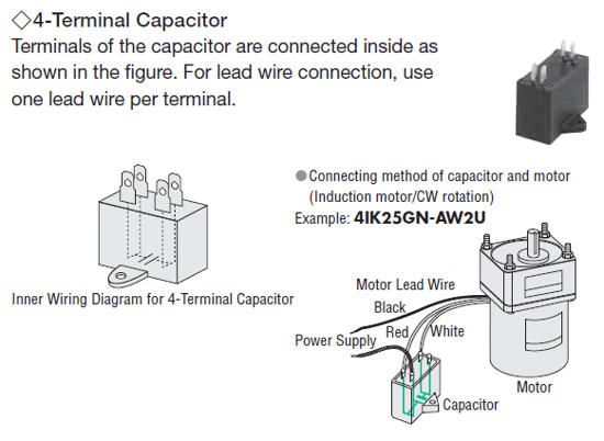
This electric motor capacitor article series explains the selection, installation, testing, & use of electric motor starter start and run capacitors used on various electric motors found in or at buildings such as air conditioner compressors, fan motors, some well pumps and some heating equipment.
Ge Motor Wiring Diagram. Print the wiring diagram off plus use highlighters to trace the signal. When you make use of your finger or perhaps the actual circuit with your eyes, it is easy to mistrace the circuit. 1 trick that We 2 to printing a similar wiring plan off twice. Upon one, I'll trace the current movement, how it operates, and that ...
Wiring Diagram For 220 Volt Single Phase Motor Http Bookingritzcarlton Info Wiring Diagram For 2 Electrical Diagram Electric Motor Electrical Wiring Diagram . Pin On Electrical Technology . Stunning 230v 3 Phase Motor Wiring Diagram 51 On Ge Dryer Best Of How To Wire A Electrical Circuit Diagram Electrical Diagram Diagram . Awesome Ge Electric ...

Typical - wiring diagram for the central locking, burglar alarm, on-board computer, additional heater end digital clock 10 Typical - headlighl washer syslem wiring diagram 13 Typical - electric window system wiring diagram 15 Typical - air conditioning system wiring diagram 17 Typical - wiring diagram for heated seats 19
General Electric motor wiring. I was just given an old cast iron air compressor. It has a general electric motor on it. Motor specs. Tri-clad capacitor motor. It has ten wires coming out of the motor. The wires are numbered. They are currently connected as follows…. 1/black from cord, 2/3, 4/white from cord, 5/10, 6/7, 8/9, green from cord is ...

If you cannot locate the wiring diagram on your appliance, you can call the GE Appliances Answer Center to obtain one. You will need to have your complete model number. The diagram may be mailed or e-mailed. You can reach us by dialing 1-800-626-2005. We are available to handle your request Monday - Friday 8:00 a.m. - 8:00 p.m. ET, and Saturday ...

Electric motor test & repair guide: This article describes A/C electrical motor troubleshooting: here we provide an electric motor diagnostic table, a troubleshooting guide that helps diagnose and repair most electric motor problems for motors found on HVAC equipment in buildings such as air conditioners, furnace or air handler blower fans, oil burner motors, well pumps, and condensate return ...

A wiring diagram is a streamlined traditional pictorial depiction of an electric circuit. If not, the arrangement won't work as it ought to be. Ge clothes dryer wiring diagram shefalitayal. 2 = red is now connected and it should be coming from high limit. Assortment of ge dryer timer wiring diagram. Collection of ge dryer wiring diagram.

Ge Single Phase Motor Wiring Diagram. Assortment of ge single phase motor wiring diagram. A wiring diagram is a streamlined standard pictorial depiction of an electrical circuit. It shows the parts of the circuit as simplified forms, and also the power as well as signal links in between the devices. A wiring diagram usually gives details…
always use wiring diagram supplied on motor nameplate. w2 cj2 ui vi wi w2 cj2 ui vi wi a cow voltage y high voltage z t4 til t12 10 til t4 t5 ali l2 t12 ti-blu t2-wht t3.org t4-yel t5-blk t6-gry t7-pnk t8-red t9-brk red tio-curry tii-grn t12-vlt z t4 til t12 tio til
Motor Test for Series Carts: Use a floor jack under the rear end center section to lift the rear wheels off the ground. Make sure you can turn the wheels by hand. Mark and remove all four motor wires. Use the below diagram and a fully charged 12 volt car battery. Make the jumper wires using 6 gauge battery cables.

A Repulsion Electric Motor is by definition a single phase motor which has a stator winding arranged for connection to the source of power and a rotor winding connected to a commutator. Brushes and commutators are short-circuited and are placed so that the magnetic axis of the rotor winding is inclined to the magnetic axis of the stator winding.


0 Response to "37 ge electric motor wiring diagram"
Post a Comment