37 johnson bilge pump float switch wiring diagram
To attach it to another SPX Johnson Pump bilge pump, use the adapter provided. Electrical installation. See page 10-11. Ampere draw. Type. Max. Let's start with the most basic float switch: a two-wire, single-pole, single-throw float switch.The rising action of the float can either close (i.e., turn on) a "Normally Open" circuit, or it can open (turn off) a "Normally Closed" circuit.Installation scenarios might include a Normally Open float switch turning on a pump to empty a tank (Control Schematic 2), or a Normally Closed ...
Apr 28, 2020 — Wires 4 and 5 would normally connect to a float switch/water sensor. It's illogical to have the lamp connected to the auto setting, it means the ...
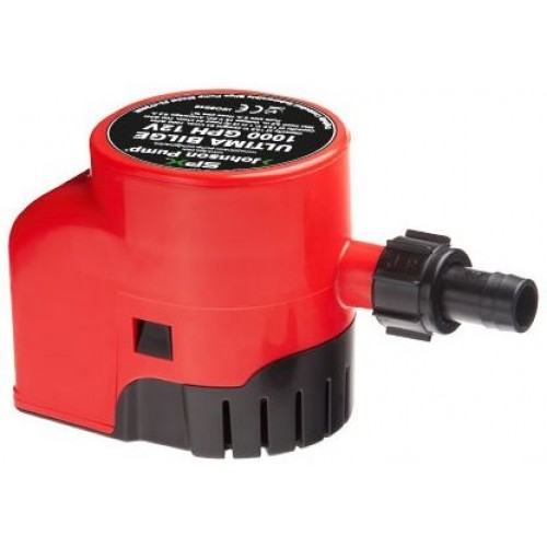
Johnson bilge pump float switch wiring diagram
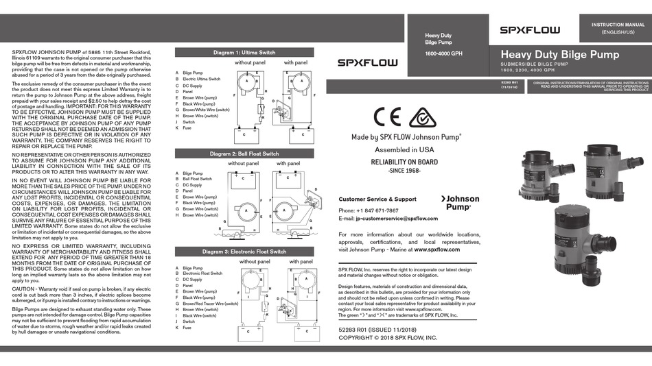
adjusts between a 12V DC and 24V DC bilge pump without ... Always install the switch according to the wiring diagram on pages 22-25.9 pages the production possibilities frontier is the boundary 17 in a production possibilities frontier diagram the attainable production points are shown as 18 in the production possibilities frontier model an un attainable po in t lies a only on the production possibilities frontier itself b only in side the production possibilities frontier c only ... Suitable for all SPX FLOW Johnson Pump submersible bilge pumps in ... bilge pump. • Always install the switch according to wiring diagram (see illustration.8 pages
Johnson bilge pump float switch wiring diagram. 7 Wire Trailer Wiring Diagram. 11/10 for 2011 wiring diagrams note: White pin to your ground.. 7 Pin N Type Trailer Plug Wiring Diagram Uk Trailer Parts from www.uk-trailer-parts.co.uk. Trailer wiring connectors various connectors are available from four to seven pins that allow for the transfer of power for the lighting as well as auxiliary functions such as an electric trailer brake ... Suitable for all SPX FLOW Johnson Pump submersible bilge pumps in ... bilge pump. • Always install the switch according to wiring diagram (see illustration.4 pages Rule Bilge Pump Wiring Diagram - One of the most hard automotive repair tasks that a mechanic or repair shop can consent is the wiring, or rewiring of a car's electrical system.The pain essentially is that every car is different. with frustrating to remove, replace or fix the wiring in an automobile, having an accurate and detailed rule bilge pump wiring diagram is critical to the ... Question: Drag the labels onto the diagram to identify structural features of epi the lium. Connective tissue Basement membrane Nucleus IDIO Lumen of duct S ... Transcribed image text: Art-labeling Activity: Classifying Epithelia Drag the labels onto the diagram to identify the types of epithelia. Color breathing is a simple stress reducing activity that may be quickly learned.
In order to be able to offer you the best attwood automatic bilge pumps available on the market today, we have compiled a comprehensive attwood automatic bilge pumps list. The best attwood automatic bilge pumps of 2021 is found after hours of research and using all the current models. Rule-Mate Bilge Pumps; Non-Automatic; Bilge Pump Switches. Float Switches; Panel Switches; Slimline Inline Submersible Pumps; 110 Volt Submersible Pumps; Aerator & Livewell Pumps; Shower Drain Pumps; Inline Blowers; Thru Hull Fittings; Seakamp Engineering. Oil Coolers; Engine Heat Exchangers; Coolant Recovery Tanks; Thermostat Housings ... Bilge Pump Location. According to 2005 Horizon 210 manual, the boat has automatic bilge pump. The manual states that the pump will turn on automatically if the water level is above the float, regardless of the position of battery switch or dashboard switch until the batteries are exhausted or water is removed. Jul 16, 2011 — I am having trouble wiring a Johnson 3-wire electronic float switch to a 3-way switch with Manual, off, and automatic bilge pump operation.
Page 158 • Catalog 110 727-446-1656 • 1-800-446-1656 • www.depco pump.com CONTENTS NEXT HOME INDEX ENGINE COOLING BACK SHURFLO REPLACEMENT PARTS Shurflo water pump wiring diagram. Turn the pump on allowing it to operate until the water is expelled. In this article we will discuss the correct way to hard wire a float switch to a submersible pump in order to achieve automatic operation. (Source: 2004 Goulds Pumps Manual, ITT Industries) In both of these cases, you must obtain the pump performance curve for the respective application, which normally comes in combined or single-line. Variety of intermatic st01 wiring diagram. Each wire set contains two insulated and one bare wire. Wire c jumper diagram 2. Strip the existing wire ends 7 16 to 7 16. An example of single pole and three way wiring follow. Doent Doent Baxi 630 Combi Wiring Diagram Heating Spare Parts Baxi Platinum Combi 33 HE Manuals and User Guides, Boiler ... Float switch not required, third wire for manual override . Rigid piping or tubing may damage the pump or the pump's discharge. A wiring diagram is a . This bilge pump has been designed to be used with flexible hose. The automatic bilge pump features two leads, an automatic (brown) and a manual override (brown with a white stripe). Rule ...
New Wiring Diagram For Multiple Lights On A Three Way Switch Diagrams Digramssample Diagramimages C Light Switch Wiring Ceiling Rose Wiring Three Way Switch. Float Switch Wiring Automatic Manual Single Phase Water Pump Controller Water Pump Youtube Electrical Circuit Diagram Water Level Switch Water Pumps. 24 3 Phase Dol Starter Control And ...
SAMSON's globe valves can be tailored to the specific control task.. The modular design of our valves enables us to provide a wide variety of valves, such as globe valves, angle valves, three-way valves, in all commonly available sizes, pressure ratings, and materials, with exchangeable trims, bellows seals or insulating sections.
To address such, the best bilge pump is a must. Reading: Best bilge pump. A bilge pump uses vacuum suction or pressure to get rid of water accumulation. By pumping the excess water, the pump prevents the boat from sinking. Otherwise, the water can result in excess weight that the boat may not support. ... Johnson Pump 28552 Marine Pump ...
Johnson bilge pump wiring cable woes advice the hull 3 way panel switch for spx flow 1600 gph instruction manual ultima electronic diode truth 36303 manualzz hurricane boat forum switches 600gph as 72303 12 v 001 float automatic submersible 1250 switchtm 1000 l450 pumps diagram to wire cartridge combo 500 12v control a on off l750 uc 24vdc iom ...
We understand this problem because we have gone through the entire Manual Bilge Pump research process already, which is why we have put together a comprehensive list of the Manual Bilge Pump available in the market today. After hours of researching and using all the models on the market, we find the best Manual Bilge Pump of 2021.
Johnson L650 Bilge Pump Our Price: .90 . Rule 800gph Bilge Pump Bilge pump installation is straightforward, The large pump can be wired to a float switch if you prefer, but I think a manual switch makes more sense. Bilge Pump Switches & Float Switches - Since 1998, iboats is the most trusted water lifestyle online store for boat parts and ...
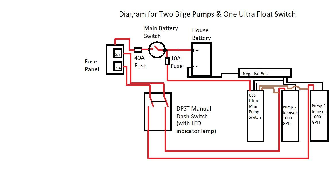
Jul 31, 2011 — My other small gripe with the diagram is that it does not show you clearly, or at all how to add a dash switch. I don't have a problem with ...
3 Phase DOL Starter Control and Power Wiring Diagram! water Pump Controller with float switch.Joint of Electric Wire with Heat Shrink Tubing. Extraordinary generator voltage regulator wiring diagram gallery size. Simplicity 700 725 b1 garden mark wiring made. 14+ Hitachi Voltage Regulator Wiring Diagram Pictures. Ih811 voltage regulator 12 volt b circuit n a l e f ig terminals 14 3 volt set ...
BILGE PUMP AUTO FLOAT SWITCH. FLOAT SWITCH TO BATTTRY. BROWN W/BLUE STRIPE. AERATOR #1 - FOREWARD/ . serial number doesn't tell anything MODEL does. Lund is still making boats and usually they will help.a tape measure will give you the length. I have a couple wiring questions on my Rebel xl. First- I want to add a 2 bank If not, call Lund and ...
Suitable for all SPX FLOW Johnson Pump submersible bilge pumps in ... bilge pump. • Always install the switch according to wiring diagram (see illustration.8 pages
the production possibilities frontier is the boundary 17 in a production possibilities frontier diagram the attainable production points are shown as 18 in the production possibilities frontier model an un attainable po in t lies a only on the production possibilities frontier itself b only in side the production possibilities frontier c only ...
adjusts between a 12V DC and 24V DC bilge pump without ... Always install the switch according to the wiring diagram on pages 22-25.9 pages








0 Response to "37 johnson bilge pump float switch wiring diagram"
Post a Comment