37 partial key er diagram
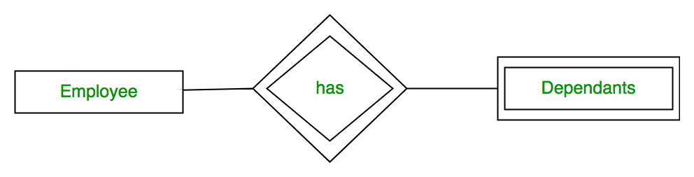
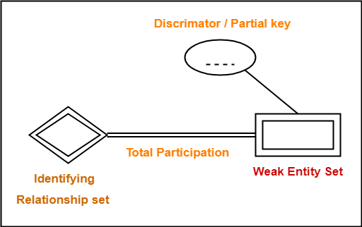
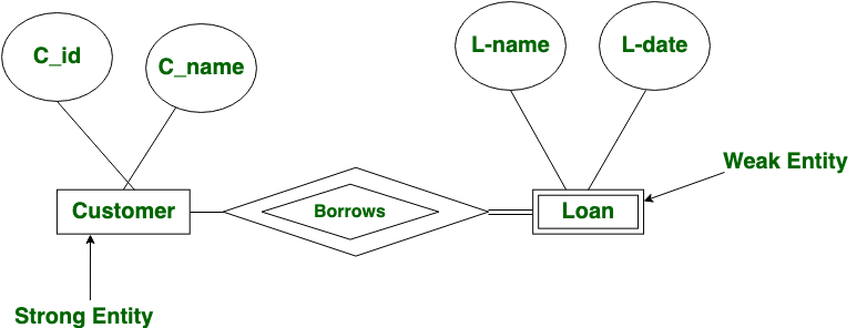
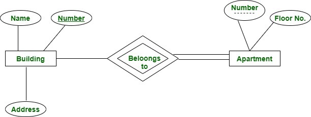
In the ER diagram, both the weak entity and its corresponding relationship are represented using a double line and the partial key is underlined with a dotted line. In the given ER diagram, Dependent is the weak entity and it depends on the strong entity Employee via the relationship Depends on.
May 31, 2010 · 2 answersIf I recall correctly UML leaves that at your discretion and does not discriminate between partial keys and other composite keys (the ...Partial Keys in a Weak Entity SetFeb 15, 2019Modelling ER diagrams with weak entitiesMar 1, 2021Abbreviation for partial keyJan 3, 2021Can we add a primary key to a weak entity?Sep 26, 2021More results from stackoverflow.com
Hotel (hotel_number, name) is a strong entity. Rooms (room_number, bed) is a weak entity whose existence depends on the existence of the hotel. 1. Hotel entity's table. 2. Room entity's table. There are two hotels with hotel_id 125 and 132. Hotel with hotel_id 125 has room numbered 101 with 3 beds and another hotel has room_number 101 with 2 beds.

Partial key er diagram
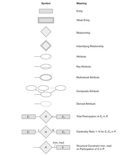
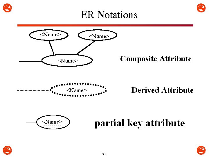
Weak entity may have a partial key, a discriminator, that unique identifies a weak entity among those related to the same strong entity. In some notations, use double rectangle for weak entity, with double diamond for relationship connecting it to its strong entity (e.g. Ricardo).
16 ER Diagrams were originally used only to represent the ER model. The ER model does not use foreign keys to represent relationships. It uses lines between boxes. The lines have some kind of indicator for cardinality at either end or both ends. Sometimes, a relationship will be indicated separately by a diamond.
For this example, {State,License#} is an alternate key. A partial key identifies a weak entity. Weak entities--those that rely on other entities ...Jul 31, 2021
Partial key er diagram.
Er Diagram Partial Key - Entity Relationship is a substantial-level conceptual details version diagram. Entity-Relation design is based on the notion of actual-community organizations as well as the relationship between them. ER modeling enables you to examine details needs systematically to generate a nicely-designed data base.
3 answersIn Entity-Relationship modeling a partial key is an attribute of a weak entity type that combined with the identifying relationships will identify entities ...
ER Diagram Examples Tutorial. This ER diagram examples-based tutorial will learn about some important concepts of entity-relationship diagrams such as ER diagram definition, ER diagram symbols and notations, ER diagram examples, and different components of an ER diagram. The entity Relation Diagram is an important model that helps design relation or table in a relational database management ...
Entity relationship model (ERM) ... that should be represented in the ER diagram. Describe the wacky Movie world . Movie . Actor Movie Actor . ... (partial key) distinguishes among elements of a weak entity set. • An entity set with a primary key is called a strong entity set
a. List the (nonweak) entity types in the ER diagram. Customer, Account, Loan, Bank. b. Is there a weak entity type? If so, give its name, partial key, and identifying the relationship. Bank_Branch is a weak entity. Its partial key is Branch-no and its identifying relationship is BRANCHES with Bank. c.
- New key can be composed of multiple attributes ... • The arrows below the dependency diagram indicate less desirable partial and transitive dependencies 15 CS275 Fall 2010 ... - Micro view of entities within ER diagram • Difficult to separate normalization process from ER modeling process 40. 11
Sep 22, 2020 — Partial Key : The set of attributes that are used to uniquely identify a weak entity set is called the Partial key.
Partial Key In Er Diagram are a crucial part in the business companies since they show to be beneficial in managing vast information inside an simple and easy successful way. It works as a model in the existing database and will allow the makers to generate an accurate design depending on the wants and demands from the company and also the project.
Entity-Relationship (ER) Diagrams Lecture 7 February 11, 2018 Entity-Relationship (ER) Diagrams ... Key Attributes The value uniquely identifies each entity All cars have a year, make, model, ... partial. February 11, 2018 Entity-Relationship (ER) Diagrams 29 STUDENT DEPT MINOR_D FACULTY
An entity relationship model, also called an entity-relationship (ER) diagram, is a graphical representation of entities (which will become your tables) and their relationships to each other. You ...
The Extended Entity Relationship Model • Result of adding more semantic constructs to original entity relationship (ER) model • Diagram using this model is called an EER diagram (EERD) • Combines some of the Object-oriented concepts with Entity Relationship concepts. 2 Entity Supertypesand Subtypes • Entity supertype
Primary key Foreign key Referential integrity Field Data type Null value 9.29.2 Discuss the role of designing databases in the analysis and design of an information system Learn how to transform an entity-relationship (ER) Diagram into an equivalent set of well-structured relations
Entity-relationship diagram - staruml documentation
ER Diagram stands for Entity Relationship Diagram, also known as ERD is a diagram that displays the relationship of entity sets stored in a database. In other words, ER diagrams help to explain the logical structure of databases. ER diagrams are created based on three basic concepts: entities, attributes and relationships.

Ppt - er-to-relational mapping principles specialization ...
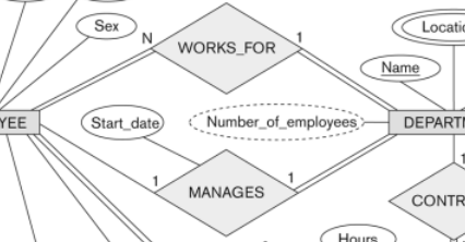
* partial participation Figures 3.12 and 3.13 In ER Diagrams: total participation is denoted by double line and partial participation by single line cardinality ratios are mentioned as labels of edges
Entity-relationship modeling
รูปที่ 1 er diagram Alternate key คือ key ทางเลือก (candidate key-primary key=alternate key) partial key คือ key อยู่ใน weak entity โดยเกิดจาก primary key ของ strong entity...

Entity-relationship diagrams | techy talks
ER Diagram Representation. Let us now learn how the ER Model is represented by means of an ER diagram. Any object, for example, entities, attributes of an entity, relationship sets, and attributes of relationship sets, can be represented with the help of an ER diagram.
Weak entity set in er diagrams - geeksforgeeks
A partial key identifies a weak entity. Weak entities--those that rely on other entities--do not have primary keys [4]. Instead, they have a partial key-- one or more attributes that uniquely identify it via an owner entity. When the word "key" is used in an E-R diagram, it usually refers to the primary key for an entity [5].
Types of keys in dbms | definitions | examples | gate vidyalay
Entity relationship diagrams in software engineering. Entity relationship diagrams are used in software engineering during the planning stages of the software project. They help to identify different system elements and their relationships with each other. It is often used as the basis for data flow diagrams or DFD's as they are commonly known.
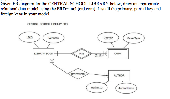
Solved given er diagram for the central school library | chegg.com
The goal of the E-R modeling process is to create an E-R diagram, ... The DEPENDENT entity does have a partial key: the attribute name, which, together with ...
Database — modeling : entity relationship diagram (erd) (part 5 ...
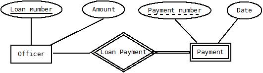
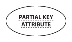
Weak entities are represented with double rectangular box in the ER Diagram and the identifying relationships are represented with double diamond. Partial Key attributes are represented with dotted lines. Example-1: In the below ER Diagram, 'Payment' is the weak entity.
Weak entity set in er diagrams - geeksforgeeks
Entity – Relationship Data Model. ▫ E-R Diagrams. ▫ Database Design Issues. ▫ Constraints. ▫ Converting E-R Model to Schemas ...25 pages
![The Entity Relationship Model - Learning MySQL [Book]](https://www.oreilly.com/library/view/learning-mysql/0596008643/httpatomoreillycomsourceoreillyimages234877.png)
The entity relationship model - learning mysql [book]
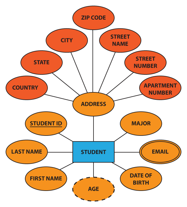
In ER diagram, key attribute is represented by an oval with underlying lines. 2. ... If some courses are not enrolled by any of the student, the participation of course will be partial. The diagram depicts the 'Enrolled in' relationship set with Student Entity set having total participation and Course Entity set having partial participation.
Introduction to database design
The primary key of W includes all the foreign key attributes added as a result of the previous paragraph, plus any partial key attributes of weak entity set W. With respect to the University E-R diagram in Figure 3.10, this step has no effect, as there are no weak entity sets.
Entity sets in dbms | gate vidyalay
•A database `schema' in the ER Model can be represented pictorially (ER diagrams). •Can map an ER diagram into a relational schema. ER Model Basics •Entity: Real-world object, distinguishable from other objects. An entity is described using a set of attributes. •Entity Set: A collection of similar entities. E.g., all employees.

Database — modeling : entity relationship diagram (erd) (part 5 ...
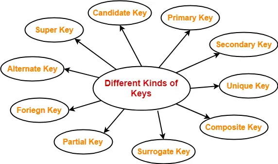
Description. Keys in DBMS is a set of attributes that can identify each tuple uniquely of the given relation. Different Types of Keys in DBMS are- Super key, Candidate key, Primary key, Alternate key, Foreign key, Partial key, Composite key, Unique key, Surrogate key, Secondary key. Author. Akshay Singhal.

Entity relationship diagram (erd) tutorial - part 2 - youtube
(a) List the strong (nonweak) entity types in the ER diagram. (b) Is there a weak entity type? If so, give its name, its partial key, and its identifying relationship. (c) What constraints do the partial key and the identifying relationship of the weak entity type specify in this diagram?
Database — modeling : entity relationship diagram (erd) (part 5 ...
In Entity-Relationship modeling a partial key is an attribute of a weak entity type that combined with the identifying relationships will identify entities of the entity type. Consider the following example ER diagram:

Relational data model and er-/eer-to-relational mapping. - ppt ...
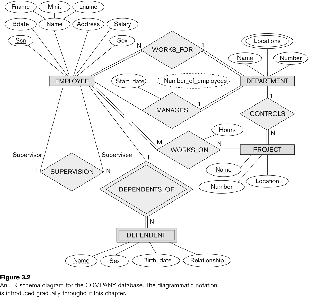
primary key SSN of the EMPLOYEE relation as a foreign key attribute of DEPENDENT (renamed to ESSN). The primary key of the DEPENDENT relation is the combination {ESSN, DEPENDENT_NAME} because DEPENDENT_NAME is the partial key of DEPENDENT. 9 The ER conceptual schema diagram for the COMPANY database

Mapping from er model to relational model - geeksforgeeks
A candidate key of an entity type is a minimal (in terms of number of attributes) superkey. ... Customers-Suppliers-Products Entity-Relationship Diagram Rectangles represent entity types Ellipses represent attributes Diamonds represent relationship types ... partial: default; each entity e 2E can participate in a relationship
Weak entity set in er diagrams - geeksforgeeks
Tugas 5_entity relationship - siti n. febriyani - universitas ...

Duadua04 blog: entity relationship diagram

Entity relationship model | symbols | example
Chen notation | vertabelo database modeler

8 - basis data : memetakan er model ke relational model - bahan ...
Chapter 7 data modeling using the entity relationship
Introduction to database design
![The Entity Relationship Model - Learning MySQL [Book]](https://www.oreilly.com/library/view/learning-mysql/0596008643/httpatomoreillycomsourceoreillyimages234879.png)
The entity relationship model - learning mysql [book]
![Solved 10.1] Answer the following questions based on BANK ER ...](https://media.cheggcdn.com/study/b72/b72426d6-f485-4530-b66a-eb4982f15a86/image.png)
Solved 10.1] answer the following questions based on bank er ...

Entity-relationship model

The entity relationship model(2)--1 reflexive rela1tionships an ...
Chen notation | vertabelo database modeler

Is it possible for a weak entity, already related to a strong ...

Share with you: entity relationship diagram (er-diagram)
Partial, unique, secondary, composite and surrogate keys in dbms ...
Key attributes in er diagrams - data science central

Database — modeling : entity relationship diagram (erd) (part 5 ...
Key attributes in er diagrams - data science central
0 Response to "37 partial key er diagram"
Post a Comment