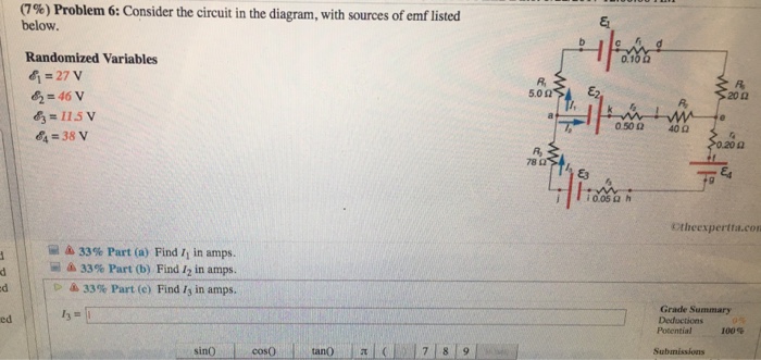
39 consider the circuit in the diagram, with sources of emf listed below.
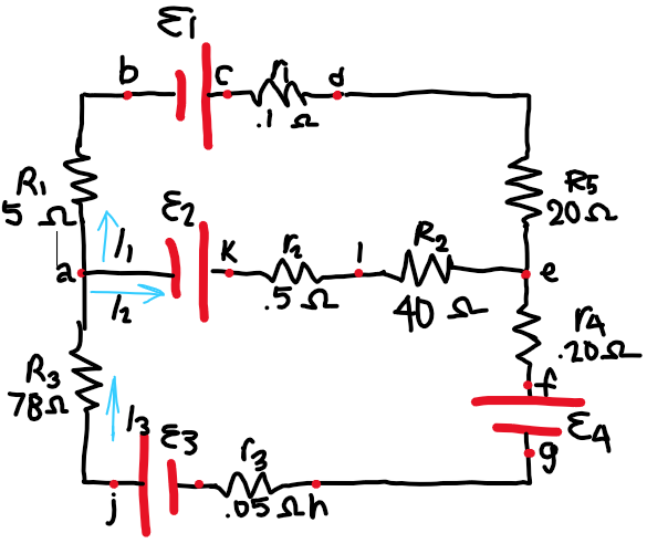
The label on a battery-powered radio recommends the use of a rechargeable nickel-cadmium cell (nicads), although it has a 1.25-V emf, whereas an alkaline cell has a 1.58-V emf. The radio has a 3.20 Ω 3.20 Ω resistance. (a) Draw a circuit diagram of the radio and its battery. Consider the circuit in the diagram, with sources of emf listed below. Randomized Variables E = 22 V Ez = 44 V 0.102 Ez = 3.5 V R 5.0 2 E2, R 202 E4 = 45 V R a e 0.50 2 40 2 14 0.20 요 R, 78 2 E3 E4 g i 0.05 2 h A. Find I in amps. B. Find I2 in amps. C. Find I3 in amps. ww. Consider the circuit in the diagram, with sources of emf listed below.
Answer to: Consider the circuit in the diagram with in the diagram with sources of emf listed below Randomized variable E 1 = 25 v E 2 = 46v ...
Consider the circuit in the diagram, with sources of emf listed below.
Consider the circuit in the diagram, with sources of emf listed. Find I 1, I 2 , and I 3 in amps. Show all work. (100%) Problem 1: Consider the circuit in ... Consider a simple circuit consisting of a battery as the emf source and a resistor of resistance R, as shown in Figure 7.2.1. Figure 7.2.1 A simple circuit consisting of a battery and a resistor Assuming that the battery has no internal resistance, the potential difference (or Problem 4: Consider the circuit in the diagram, with sources of emf listed below. Randomized Variables ℰ 1 = 25 V ℰ 2 = 44 V ℰ 3 = 14 V ℰ 4 = 28 V. Part (a) Find I 1 in amps. Numeric: A numeric value is expected and not an expression. I 1 = _____ Part (b) Find I 2 in amps. Numeric: A numeric value is expected and not an expression.
Consider the circuit in the diagram, with sources of emf listed below.. Click here👆to get an answer to your question ️ (10%) Problem 10: Consider the circuit in the diagram, with sources of emf listed below. 5.023 > E2. Randomized Variables & = 28 V E2 = 43 V Ez = 11 V E = 41 V 02 me 400 78 22 TEA W 10.050 h Electric circuits can be described in a variety of ways. An electric circuit is commonly described with mere words like A light bulb is connected to a D-cell . Another means of describing a circuit is to simply draw it. A final means of describing an electric circuit is by use of conventional circuit symbols to provide a schematic diagram of the circuit and its components. Emf circuit diagram electromagnetic ar emf detector with lm358 6 steps with pictures emf circuit diagram emf detecting wand essential scrap. Present transcribed photo text 17 difficulty 8. consider the circuit in the chart with sources of emf listed below. Emf circuit diagram cell phone detector or emf detector circuit. Problem 6: Consider the circuit in the diagram, with sources of emf listed below Randomized Variables EI-25 V & 49 V 0.102 5.0 Ω 20Ω R2 0.50 Ω 40Ω 4 31 V 0.20 Ω Ra 9 ¡0.05 Ω h Otheexpertta.com Part (a) Find /1 in amps. . tan( cos(0) cotan0asin) acos(0 sin() 4 5 6 *1 23 0 atan()acotan( sinh() cosh)tanh) cotanh O Degrees O Radians BACKSPACE CLEA Submit Hint I give up!
Share free summaries, lecture notes, exam prep and more!! Circuits ÎThe light bulbs in the circuits below are identical. Which configuration produces more light? (a) circuit I (b) circuit II (c) both the same Circuit II has ½ current of each branch of circuit I, so each bulb is ¼ as bright. The total power in circuit I is thus 4x that of circuit II. Consider the circuit in the diagram with sources of emf listed below. Consider the circuit in the diagram with sources of emf listed below. Show more 1 consider the circuit in the diagram below in which r 10 ω. With resolution 1584px x 1379px. Ohm S Law Electric Circuits Siyavula Solved 10 Problem 11 Consider The Circuit In The Diag The circuit diagram below shows two emf sources and a bulb connected in parallel. Also connected in the circuit is a resistor with resistance R = 0.2? . The ...1 answer · Top answer: I1 = -0.21 A I2 = 0.22 A IS = I1+I2 = 0.01A 270 60.lon LI II Egon ww 1 410 0.son to for 3o. 2o1 L-I 78r 34 13 = (1, +12) CAT 39v 17.50 I o.oor loop ...
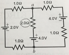
Consider the circuit shown in the figure below. Find (a) the potential difference between points a and b and (b) the current in the 20.0-V resistor. Consider the circuit in the diagram, with sources of emf listed below. Randomized Variables E = 22 V Ez = 44 V E3 = 3.5 V 0.10 2 R 5.0 Ω E2 202 E4 = 45 V R a 0.50 2 40 2 0.20 요 R 78 2 E3 i 0.05 2 h A. Find Ij in amps. B. Find I2 in amps. C. Find I3 in amps. Alternating-Current Circuits 12.1 AC Sources In Chapter 10 we learned that changing magnetic flux can induce an emf according to Faraday's law of induction. In particular, if a coil rotates in the presence of a magnetic field, the induced emf varies sinusoidally with time and leads to an alternating current (AC), and provides a source of AC ... Transcribed image text: Consider the circuit in the diagram, with sources of emf listed below. Randomized Variables epsilon_1 = 26 V epsilon_2 = 43 V ...
5-a) An RL circuit is driven by an AC voltage source as shown in the figure. (Figure 1). On the phasor diagram below, adjust the phasor that represents the voltage across the resistor (VRVRV_R) at the instant indicated to the proper orientation.
Answer to: Consider the circuit in the diagram, with sources of emf listed below. Randomized variables: \Epsilon_1 = 22 V, \Epsilon_2 = 49V,...

2. The source that maintains the constant currentin a closed circuit is called a source of "emf." a) One can think of such a source as a "charge pump" =⇒ forces electronstomove in adirection oppositetheE-field, hence current, inside a source. b) The emf, E, of a source is the work done per unit charge =⇒ measured in volts. c) A ...

Multi-loop Circuits and Kirchoff's Rules. 7-13-99 Before talking about what a multi-loop circuit is, it is helpful to define two terms, junction and branch. A junction is a point where at least three circuit paths meet. A branch is a path connecting two junctions. In the circuit below, there are two junctions, labeled a and b.
Question: (9%) Problem 6: Consider the circuit in the diagram, with sources of emf listed below Randomized Variables 81-29 V 0.1 R, 20Ω 83-6.5 V 84-43 V 0.50 Ω 40Ω 020 Ω 78 Ctheexpertta.c Li 33% Part (a) Find 11 in amps. 33% Part (b) Find 12 in amps. 33% Part (c) Find 13 in amps.

Consider the battery in the figure. The voltage of the battery is defined as the difference in electric potential between its positive and negative terminals: i.e., the points and , respectively.As we move from to , the electric potential increases by volts as we cross the emf, but then decreases by volts as we cross the internal resistor. The voltage drop across the resistor follows from Ohm ...
Problem: Consider the circuit in the diagram, with sources of emf listed below.Randomized Variablesℰ1 = 21 Vℰ2 = 49 Vℰ3 = 9.5 Vℰ4 = 39 Va) Find I1 in amps.B) Find I2 in amps.C) Find I3 in amps.

(109) Problem 7: Consider the circuit in the diagram, with sources of emf listed below. Randomized Variables 8j = 23V 62 = 46 V 6=105V 64 =46V Od 20 !Jun 25, 20214 answers · Top answer: this question is asking us to solve a system of equations by using an inverse of a coefficient ...
Consider the circuit shown in Figure P28.9. Find ... In (c), the source of emf is traversed in the direction of the emf (from - to +), and the ... Draw the circuit diagram and assign labels and symbols to all known and unknown quantities. Assign directions to the currents.
Answer to: Consider the circuit in the diagram, with sources of emf listed below. Solve for I1, I2, and I3. By signing up, you'll get thousands of...
Question: (17%) Problem 2: Consider the circuit in the diagram, with sources of emf listed below Randomized Variables 0.10 =27 V R &= 41 V E2 5.0 Ω 20Ω R 10.5 V 0.50 40 4=27 V 78 Ω i 0.05 h Otheexpertta.com A 33% Part (a) Find /1 in amps Grade Summary Deductions 0% Potential 100% Submissions sin( tan acos( sinh cotanh cos( ( 7 HOME JT ...
(7%) Problem 3: Consider the circuit in the diagram, with sources of emf listed below, ca 0.10 0 Randomized Variables E = 22 V 5.0 20 0 EL = 42 V [T, ...
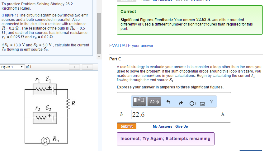
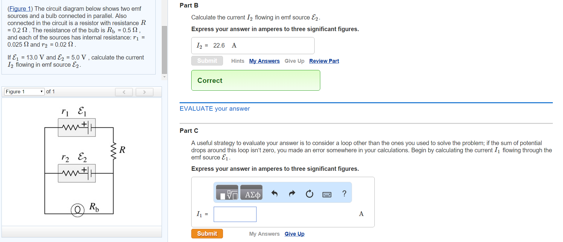
The circuit diagram below shows two emf sources and a bulb connected in parallel. Also connected in the circuit is a resistor with resistance R = 0.2 . The resistance of the bulb is Rb = 0.5 , and each of the sources has internal resistance: r1 = 0.025? and r2 = 0.02 ? .

Solution for (6%) Problem 16: Consider the circuit in the diagram, with sources of emf listed below. Randomized Variables 0.10 2 E1 = 22 V E2 = 44 V Ez = 3.5 V…

Solution for Problem 4: Consider the circuit in the diagram, with sources of emf listed below. Randomized Variables 0.10 2 E1 = 29 V Ez = 47 V Ez = 7.5 V E4 ...
Problem 4: Consider the circuit in the diagram, with sources of emf listed below. Randomized Variables ℰ 1 = 25 V ℰ 2 = 44 V ℰ 3 = 14 V ℰ 4 = 28 V. Part (a) Find I 1 in amps. Numeric: A numeric value is expected and not an expression. I 1 = _____ Part (b) Find I 2 in amps. Numeric: A numeric value is expected and not an expression.
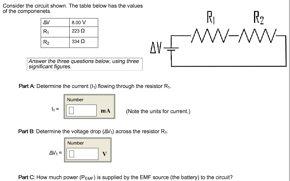
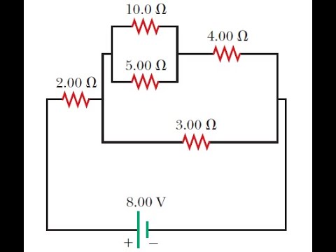
Consider a simple circuit consisting of a battery as the emf source and a resistor of resistance R, as shown in Figure 7.2.1. Figure 7.2.1 A simple circuit consisting of a battery and a resistor Assuming that the battery has no internal resistance, the potential difference (or

Consider the circuit in the diagram, with sources of emf listed. Find I 1, I 2 , and I 3 in amps. Show all work. (100%) Problem 1: Consider the circuit in ...


0 Response to "39 consider the circuit in the diagram, with sources of emf listed below."
Post a Comment