39 pressure sensor circuit diagram
May 3, 2021 Author. Zachary Long. Home » Wiring Diagrams » Maxxforce Engine Sensors Location. international maxxforce dt icp sensor location. maxxforce 11 13 and 15 manuals. maxxforce 13 engine sensor locations. We collect lots of pictures about Maxxforce Engine Sensors Location. and finally we upload it on our website.
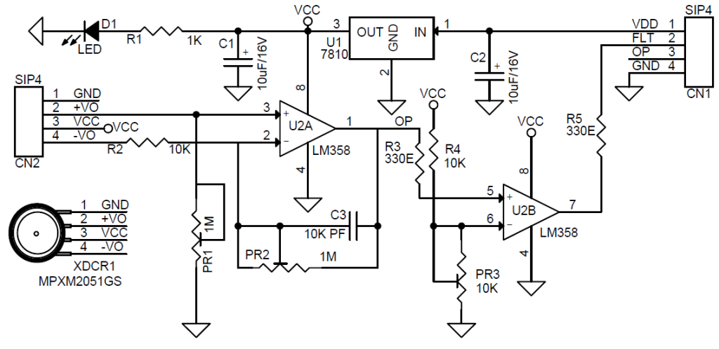
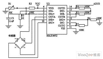
The signal conditioning circuit shown in Figure 1 provides a precision constant current source for sensor excitation and an instrumentation amplifier with the ...5 pages
Light Sensor Circuit Working Operation. The light sensor circuit is an electronic circuit designed using (light sensor) LDR, Darlington pair, relay, diode, and resistors which are connected as shown in the light sensor circuit diagram. A 230v AC supply is provided to the load (in this case, the load is represented with a lamp).
Pressure sensor circuit diagram
The sensor can be defined as a device which can be used to sense/detect the physical quantity like force, pressure, strain, light etc and then convert it into desired output like the electrical signal to measure the applied physical quantity. In few cases, a sensor alone may not be sufficient to analyze the obtained signal.
General purpose circuit of the simple pressure sensor alarm is built around a couple of readily available cheap components. Working of this circuit is ...
September 16, 2021. Oil Pressure Sensor Wiring Diagram- Delightful in order to my own website, in this particular time I will demonstrate regarding oil pressure sensor wiring diagram. And after this, this can be a 1st graphic: Lower Sensor Branch Wiring Diagram â Junk Yard Zetec from oil pressure sensor wiring diagram, source:Junk Yard Zetec ...
Pressure sensor circuit diagram.
Throttle Position Sensor Wiring Diagram - dodge throttle position sensor wiring diagram, ford throttle position sensor wiring diagram, gm throttle position sensor wiring diagram, Every electric structure is composed of various different components. Each part ought to be placed and linked to different parts in particular manner. Otherwise, the arrangement won't work as it ought to be.
Below is the circuit diagram or connection for IoT Based Air Pollution/Quality Monitoring System. There are 3 sensors which is connected to wifi chip NodeMCU ESP8266 12E. PMS5003 Sensor works on UART Communication. It has 8 pins and counting is done from the right.
In addition to traditional weather forecasting applications, these sensors also find use in smartphones for navigation. Since air pressure decreases with altitude, the information from a high-resolution barometric pressure sensor can be used to determine height above sea level. Typical application circuit and block diagram of BM1390GLV.
Pressure Sensor Circuit Diagram February 18, 2021 admin Pressure Sensor This sensor is based on the Lucas NovaSensor NPC-410 Series pressure sensor. The circuit below contains the usually powered sensor interface, but I used an LM358 dual opamp in place of the usual LM324. The 78L05 regulates the voltage from the RCX down to 5V.
The BMP180 is a Digital Barometric Pressure Sensor from Bosch. It is an ultra-low power device based on piezo resistive MEMS device. It can measure the atmospheric pressure in the range of 300 hPa to 1100 hPa. In addition to pressure, the BMP180 Sensor can also measure Temperature in the range of 0 0 C to 65 0 C.
The BMP180 is a Digital Barometric Pressure Sensor from Bosch. It is an ultra-low power device based on piezo resistive MEMS device. It can measure the atmospheric pressure in the range of 300 hPa to 1100 hPa. In addition to measuring pressure, the BMP180 Sensor can also measure Temperature in the range of 0 0 C to 65 0 C. Since BMP180 measures ...
The output voltage of the pressure sensors is read using a multimeter. The results of both pressure sensors are plotted on a graph of the pressure versus output ...
If you're applying a quite a bit of pressure to the FSR so that the resistance drops to 50,000 ohms our equation will be (100,000 / (100,000 + 50,000)) * 5 = ~3.3 volts. This should read about 700 on the analog pin. Circuit Diagram As I mentioned above, the circuit diagram for a force sensing resistor is really straight forward with the Arduino.
Registered. Joined 10 mo ago. ·. 4 Posts. Discussion Starter · #1 · 10 mo ago. Only show this user. Does anyone have, or know where I can get a copy of the 2021 Rzr xp4 turbo wiring schematic? I destroyed my tmap sensor plug installing a boost pipe and intake pipe kit. Ripped the wires out of it trying to remove the clip 🤦🏼♂️.
Aug 1, 2012 — When is a pressure sensor active and when passive? Illustrative circuit diagram with a 2-wire pressure sensor, a 4-wire pressure sensor and ...
This is pressure sensor signal conditioning circuit. It is simple and inexpensive circuit because it has small geometry and simple pressure sensor.
IOT Live Weather Station Monitoring Using NodemCU ESP8266. This post is all about IoT based Live Weather Station Monitoring Using NodemCU ESP8266.We will interface DHT11 Humidity & Temperature Sensor, BMP180 Barometric Pressure Sensor, and FC37 Rain Sensor with NodeMCU ESP8266-12E Wifi Module.We will measure humidity, temperature, Barometric pressure, and rainfall and upload the data to a web ...
Connectdetect®
Connecting Heart Rate sensor and BME280 sensor. The MAX30100 is an integrated pulse oximetry and heart-rate monitor sensor solution. It combines two LEDs, a photodetector, optimized optics, and low-noise analog signal processing to detect pulse oximetry and heart-rate signals.
Pressure sensor – electronic circuit diagram
Download scientific diagram | pressure sensor circuit diagram. Most pressure or force transducers take the the bandwidth of the sensor transducer signal is generally narrow and the sensitivity to noise is high. Only for the type of truck 6×2. These dtcs are set if the fuel pressure sensor output voltage is wiring diagram.

Pressure sensor & wiring diagram
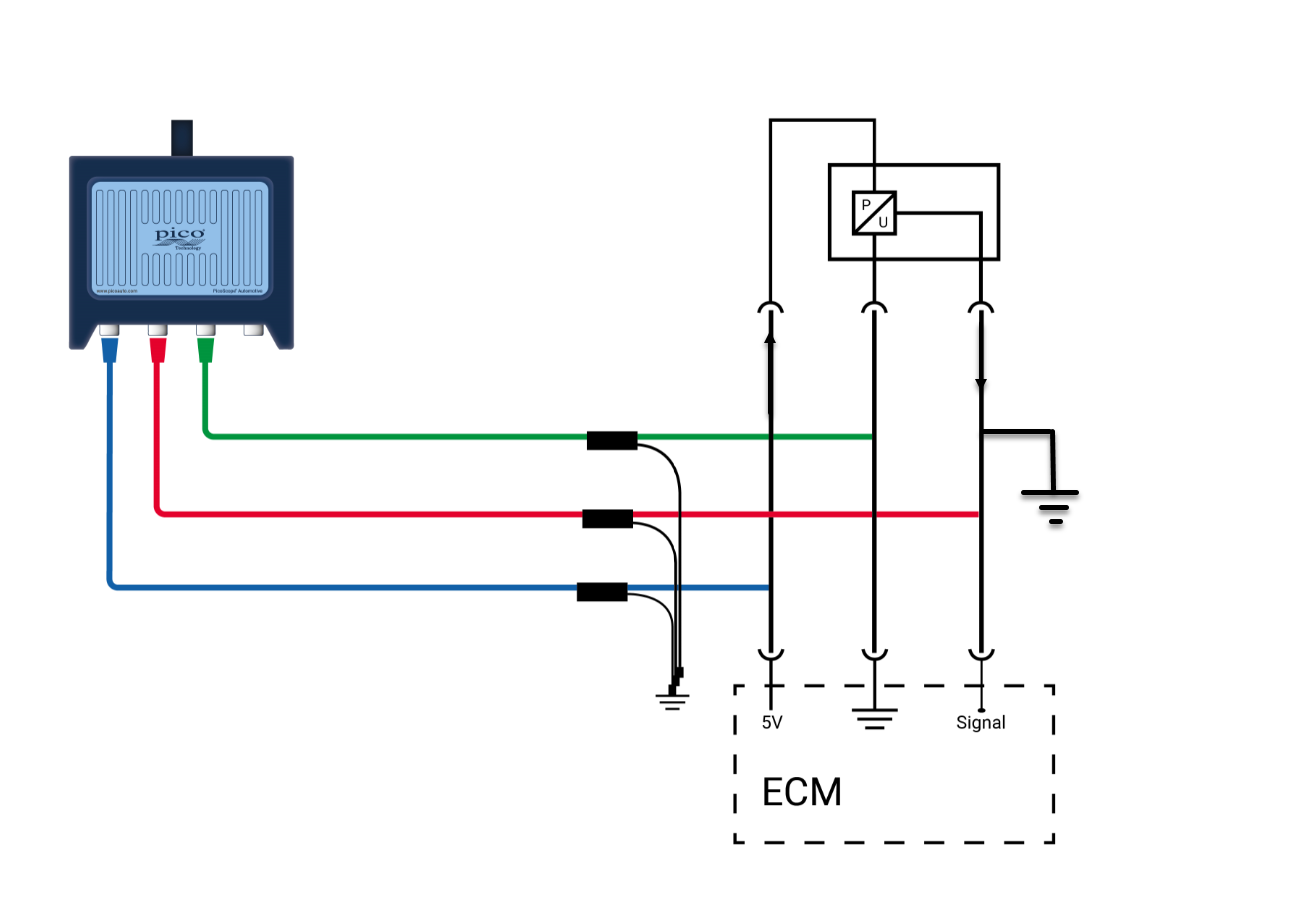
The D type EFI system eliminates the use of an air flow meter and uses a manifold absolute pressure sensor as a load measurement device instead. Because pressure in the intake manifold is proportional to the amount of air entering it, the manifold absolute pressure sensor is used to measure air intake volume in the D type EFI system. This sensor compares a variable pressure inside the intake ...
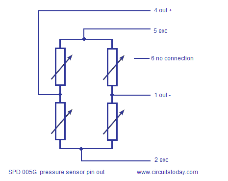
Interfacing spd005g pressure sensor to arduino-circuit ...
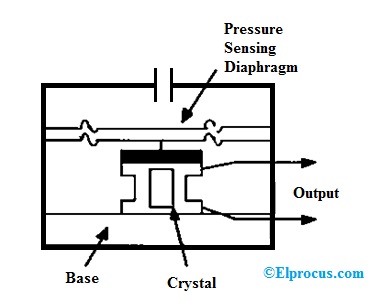
May 19, 2019 — The working of this circuit starts with Piezoelectric transducer element which is used as Pressure sensing element in our circuit. Piezo sensors ...

24pc honeywell pressure sensor – mechlectrical instrumentation
When the ignition SW is turned on and the brake pedal is pressed (Stop lamp SW on), if the stop light circuit is open, the current flowing from TERMINAL 7 of the light failure sensor to TERMINALS 1, 2 changes, so the light failure sensor detects the disconnection and the warning circuit of the light failure sensor is activated.

Optical pressure sensor-working,construction,circuit diagram
by OI Amplifier — Flexible, 4 mA-to-20 mA Pressure Sensor Transmitter with Voltage or Current Drive ... and schematics in the CN0295 design support package:.6 pages
Differential capacitance pressure sensor circuit
Board mount pressure sensors, as the name implies, are pressure sensors designed to be mounted on a PCB (Printed Circuit Board), thus becoming an integrated part of an electronic assembly. While some sensors are designed to evaluate the physical contact pressure between a sensor and a solid object, others are specifically intended to measure ...
Simple pressure sensor amplifier & over pressure switch ...
Chapter 16 practice quiz, review questions & workbook. Each horizontal line on a ladder diagram represents an individual _____. A device used mainly to detect a particular condition, such as heat or pressure is a _____. Nice work! You just studied 99 terms! Now up your study game with Learn mode.

Simplified electrical circuit diagram of a piezoresistive ...
Differential pressure level sensor/transmitters should also be used for the accumulator (the vessel that collects condensed distillate) and bottom of the column because maintaining these levels is essential for reliable operation of the column. If flooding is an issue, a pressure differential across the column should indicate the onset of flooding.
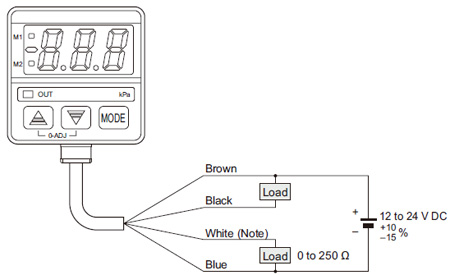
![Digital Pressure Sensor [For Gas] DP-0 I/O Circuit and Wiring ...](https://www3.panasonic.biz/ac/ae/fasys/pressure/pressure/dp-0/circuit/images/pic01.jpg)
Digital pressure sensor [for gas] dp-0 i/o circuit and wiring ...
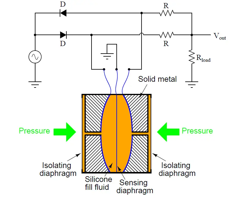
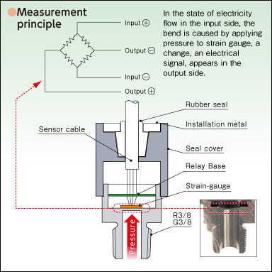
The elastic material can be used to form a thin elastic membrane which is known as a diaphragm. The electrical device which is united by the diaphragm to make a ...
Pressure transducer : circuit diagram, types and its applications
Circuit Diagram Save Subscribe Click to enlarge. Velostat pressure sensor (described in the next step) connected to GND and pad marked D9 (this pin is also A9, and we will be using it as an analog input). NeoPixel strip DIN -> FLORA D6 NeoPixel strip +5V -> FLORA VBATT NeoPixel strip GND -> FLORA GND (any)

Code no. p0192: rail pressure sensor circuit low input
2.1. Capacitive Sensor. There are various types of capacitive sensors; however, for the convenience of understanding, if we model the capacitance between two flat electrodes (C = εA/d); the capacitive sensors can measure the permittivity, the distance between the two electrodes, or the area change caused by the change in the physical quantity to be measured; the capacitive sensors can be ...

Schematic diagram of pressure transducer. (a) detail of ...
Pulse Sensor Circuit Diagram. The interfacing of the pulse sensor using an Arduino is shown below. Here, the sensor used in this is plug & play heart rate sensor. This kind of sensor is quite simple to understand as well as operate. Place the pulse sensor on the finger & it will detect the heartbeat by detecting the change within the light from ...

Gauge pressure sensors | the design engineer's guide | avnet ...
Find circuits of your needs we have circuits on every topic and field- Circuit diagram is a graphical representation of an electrical circuit. Monday, December 13 2021. Latest Projects. 12V DC to 220V AC Converter [Tested Circuit] ... How to use LDR Sensor in Proteus Schematic Circuit Diagram.

Amplified low pressure sensors - amphenol all sensors ...
Code was P06DE - Engine Oil Pressure Control Circuit Stuck On and the recommendation on my OBD scanner is to change the oil pump. With the Jeep idling, I was getting an oil pressure of around 22-25 psi. Engine temperature was around 206 degrees. Decided to keep driving while keeping an eye on the oil pressure and engine temperature.
Pressure sensors
The wire colors that come into the board from the sensor are as follows: S+ - yellow S- - white I+ - red I- blue. Now, S+ is connected through a 49.9k resistor to Pin 5 of the IC and S- is connected through a 49.9k resistor to Pin 6.

Pressure sensor alarm
All the details linked to this circuit is give below, Such as Schematic diagram, components list. What is a Touch Sensor Circuit? Touch sensors work similar to a switch. When they are subjected to touch, pressure or force they get activated and acts as a closed switch. Only using 3 transistors you can create this circuit.

Force / pressure switch circuit using fsr - gadgetronicx ...
The simple circuit diagram can be seen below: In this configuration, the hall effect sensor will convert a magnetic field within a specified proximity and will convert it into a linear analogue signal across its "out" pin. This analogue signal can be easily used for driving a load or for feeding any desired switching circuit.
Kia rio: brake booster vacuum pressure sensor: circuit ...
Diagnostic trouble code (DTC) P0191 stands for "Fuel Rail Pressure Sensor Circuit "A" Range/Performance." It indicates a potential abnormality in the fuel rail pressure readings. Because of either a mechanical or electrical problem, the signal sent by the fuel rail pressure sensor doesn't match the value the PCM expects to see.
Micro-differential pressure high-precision digital pressure ...

4 wire pressure transducer wiring diagram | transducer ...

Differential pressure sensors | the design engineer's guide ...
Programmable pressure transducer circuit – electronic circuit ...
Simple pressure sensor amplification circuit diagram ...
Pressure sensor alarm circuit schematic under repository ...

Suppressing interference in a pressure sensor circuit ...

Ep1722211a2 - linearizer circuit for a capacitive pressure ...
Sensor basics: types and list of sensor based latest applications
Kia carens - rail pressure sensor (rps) schematic diagrams ...
Structural schematics for pressure sensors | valcom co.,ltd ...

Pressure sensor alarm circuit schematic

A) circuit diagram of pressure sensors, (b) actual pressure ...

Fsr velostat pressure sensor circuit with lm324 opamp ...

Circuit diagram of pressure sensor | download scientific diagram
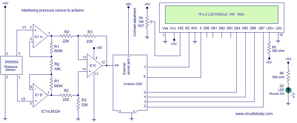
Interfacing spd005g pressure sensor to arduino-circuit ...

Pressure sensors | the design engineer's guide | avnet abacus
Pressure sensor - sensor circuit - circuit diagram - seekic.com
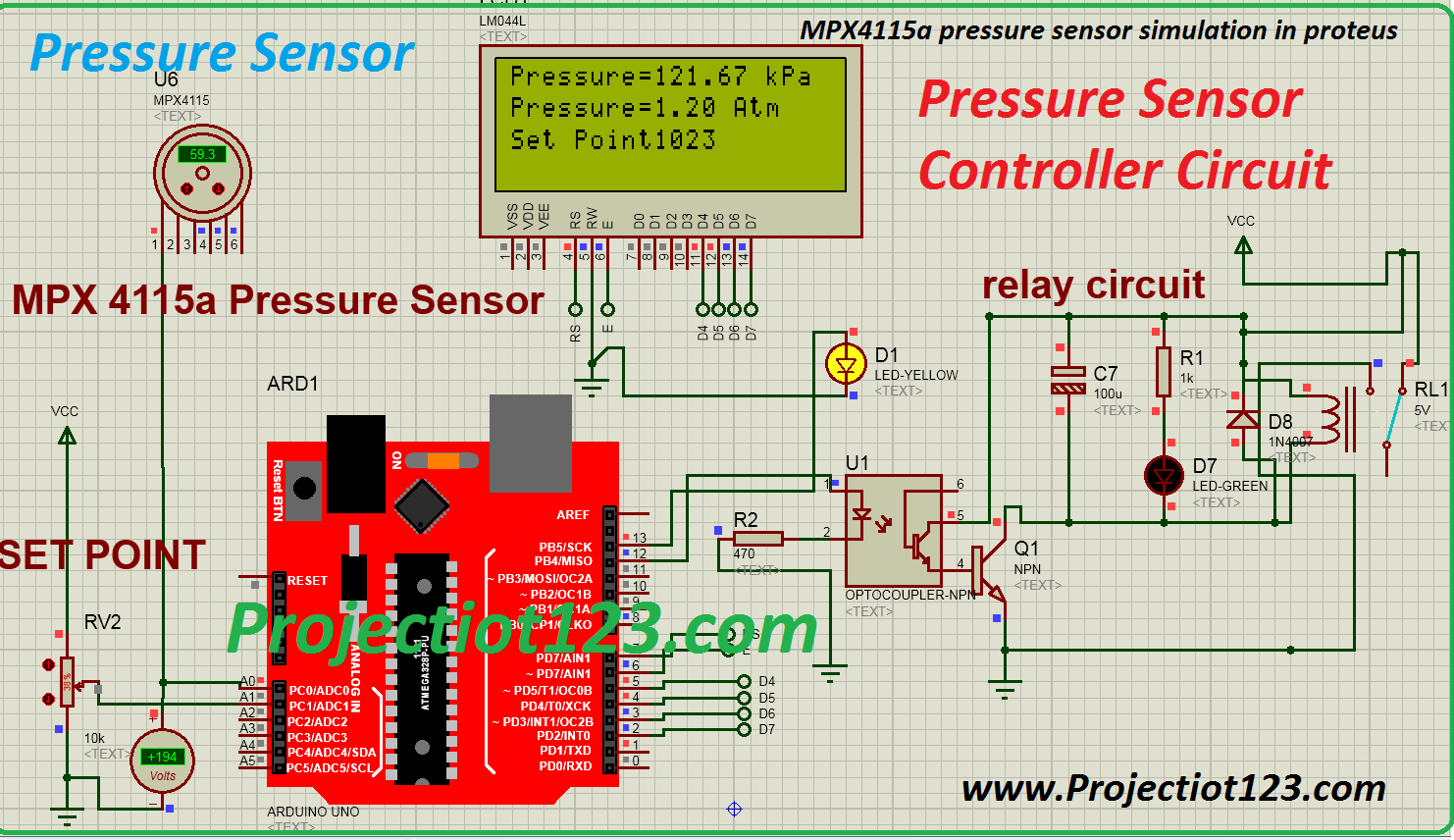
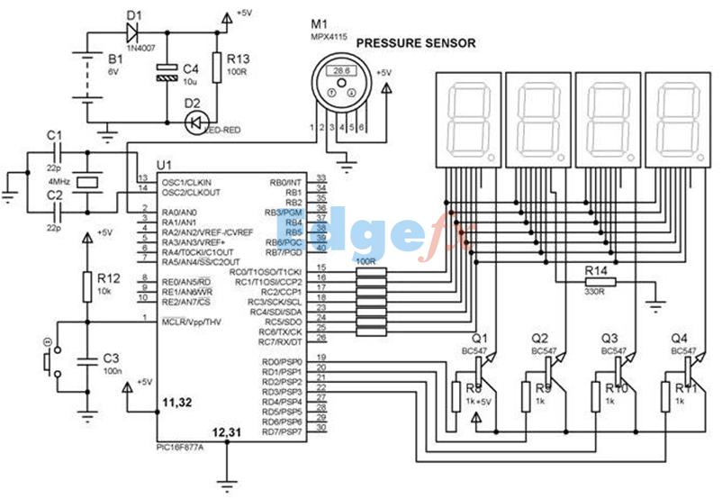
Mpx4115a pressure sensor circuit arduino specification pinout ...
0 Response to "39 pressure sensor circuit diagram"
Post a Comment