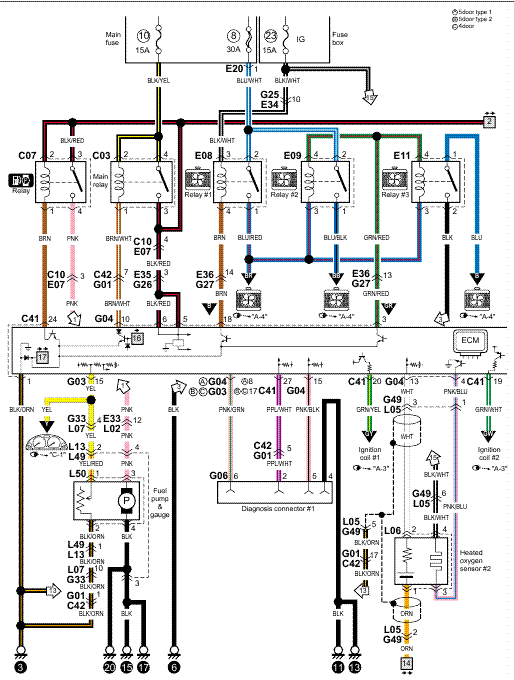
36 grasslin timer wiring diagram
Grasslin dtmv40 series timer operating instructions manual manualslib intermatic dtav40 installation pdf heatcraft dtsz defrost and operation manualzz time controls hvac r hv ac owner s t 49f wiring diagram swapping on true t49f freezer from dtsx im 120tm to a supco s814100 i need wirecolor auto voltage multi 40 the first only product catalog pages 101 150… Read More » Request Grasslin FM/1STUZ-120: Module, Timer; Surface Mount; 1/4 in. Quick-Connect; SPDT; 24/120/240 VAC online from Elcodis, view and download FM/1STUZ-120 pdf datasheet, Digital Signal Controllers (DSC) specifications.
August 2 2021 on Ts18 Timer Wiring Diagram. The above circuit diagram is for the 1-minute timer circuit. Timer Testing Wiring Diagram Earth Bondhon Timer Digital Timer Little Current Grasslin timer need to no what wires go were there are 4 wires coming out the timer red and brown together white and. Timer switch wiring …

Grasslin timer wiring diagram
Pool pump timer bypass in 240v system intermatic wiring t104 off with heater delay circuit basic repair t104r won t turn on grasslin ground i have a sul181h electrical 7 days dual gpo hydroxypure Guidance Needed For Wiring Of Pool Pump Timer Bypass In 240v System Diy Home Improvement Forum Intermatic Pool Timer Wiring […] Supco Heavy Duty 8 Hours 25 Minutes Refrigerator Tmdc Defrost Timer 825 1 China And Made In Com. Supco S8145 20 Complete Commercial Defrost Timer Replaces Paragon 8145 Canada. T 49f Wiring Diagram Swapping Timer On True T49f Freezer From Grasslin Dtsx Im 120tm To A Supco S814100 I Need Wirecolor. Replacing a Grasslin time clock in your saltwater chlorinator? Here are the instructions on setting the clock. Grasslin time clocks are available from Direct...
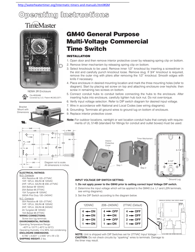
Grasslin timer wiring diagram. Wiring Grasslin Pool Timer. Talento 111 Mini Grässlin Time Clock Relay Din Rail Day 1 Make Contact No Distrelec Germany. Intermatic Grasslin Talento Smart C25 Operating Instructions Manual Manualzz. Talento 111 Mini GrÄsslin Timer 30min 24h Spst No 250vac 16a 220 240vac Din 25 55 C 01 06 0004 1 Tme Electronic Components Wfs. Grasslin Pool Timer Wiring Diagram. Wiring grasslin pool timer grässlin uk ltd installation amp operating instructions intermatic fm1stuzh 240u 21a 24 120 208 240v analog or mechanical switch manual manualzz time graslin analogue german onlinepool co za pf1102t and pf1103t control best on timers online guaeed tg wastewater help how to wire ... True 831994 Dtsx B 120 Tm Defrost Timer By Grasslin 245 00 Picclick. Heatcraft grasslin dtsz defrost timer t 49f wiring diagram swapping on intermatic dtav40 series installation operating instructions multi voltage dtsx b 240 icm550 warning risk of fire or electric shock time controls hvac r timers gra catalog 2004 norlake 127147 refrigeration a c maintenance s dtmv40 brochure 120 tm by ... Furnish and install a Grasslin GM40 _ Multi-Volt Series 24 hour or (7 day) time switch with captive trippers and quartz or syn-chronous drive. Input voltage shall be 120, 208/240 or 277VAC ... GM40 TYPICAL WIRING DIAGRAMS 3 TIMER 120VAC H N T L1 L2/N NC NO COM NC2 NO2 COM2 LOAD T TIMER 120VAC H N T L1 L2/N NC NO COM NC2 NO2 COM2 LOAD #1 T LOAD ...
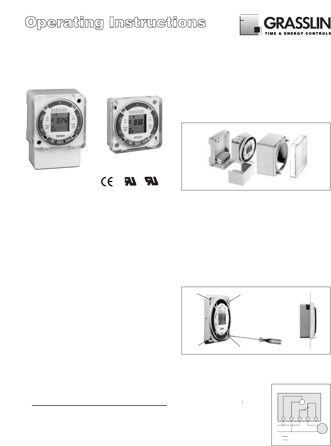
GM40AV series timer pdf manual download. ... Grasslin GM40AV series Installation And Operating Instructions ... wiring diagrams on page 3). GRASSLIN. Operating Instructions. FM/1 digi 20 ... Wiring connections: 1/4" quick connects ... The timer cannot be programmed unless.4 pages 24 Hour or 7 Day Time Switches FM1D20A (surface mounting) FM1D20E (flush mounting) APPLICATION ... Connect wiring according to the wiring diagram. The terminals on the Digi 20A sub-base will accommodate 10 to 24 AWG wire. Terminal Connections B A A B N.C. Contact-8 A, 24 V dc Pilot Duty Jan 23, 2019 · Avr As440 Wiring Diagram; 2006 Larson 180 Sei Wiring Diagram; Ford 9n 12 Volt Conversion Wiring Diagram; Detroit Series 60 Ecm Wiring Diagram; Grasslin Timer Wiring Diagram; 311-0041-130 Wiring Diagram; Fusion Vs Fission Venn Diagram; Danby D9604w Wiring Diagram; 4.3 Vortec Vacuum Diagram; Grote Tail Lights Wiring Diagram; 1988 Sea Ray 4.3 ...
Wiring Connections Screw terminals for up to #12 AWG wire Ship Weight.66 lbs (.29 kg) Warranty 1-year limited Model # Input Voltage Total Cycle Time Timing Interval per Tripper FM1S12HU-120U 120 VAC, 60 Hz 12-Hr 7.5-Min FM1S12HU-120U 21 A, 12-Hour Repeat Cycle Time Switch The FM1S12HU-120U is a sychronous motor driven grasslin timer need to no what wires go were there are 4 wires coming out the timer red and brown together white and. Grässlin UK Connect wiring in accordance with wiring diagram. Do not combine timer to control a load on a separate supply circuit, which can be a different. The DTAV40 Defrost Timer is equivalent in function, terminal identification (with appropriate terminal block label attached), and wiring to the Paragon 8140 and Precision 6140 series Defrost Timers. The DTAV40 may also be used to replace Paragon 8040 and Precision 6040 series time terminated defrost timers. Grasslin Controls 40a Defrost Timer Wiring Diagram. Grasslin dtmv40 series timer operating instructions manual manualslib intermatic dtav40 installation pdf defrost auto voltage owner s time controls hvac r hv ac multi 40 the first and only manualzz heatcraft dtsz operation warning risk of fire or electric shock caution damage to precision ...
selective focus photo of woman with sunglasses
25175 Control Panel Wiring Diagram (using Grasslin time clock part no. DIGI 42/2) 8700A Control Panel Wiring Diagram. 3 Hand Key 1 Hand Key 2 Reset Key "On" Symbol Program Key Clock Key Channel 1 Symbol Day Key Minute Key Hour Key "Off" Symbol Channel 2 Symbol MF1070-4 6/97 Time Clock Programming Instructions

Grasslin Defrost Timer Dtsx B 240 Wiring Diagram - Wiring ...
Guidance needed for wiring of pool pump timer bypass in 240v system diy home improvement forum grasslin a doityourself com community forums i have sul181h electrical two wires coming from my power source and going to outdoor with heater delay circuit intermatic t104 off tripper turns the clock waco need help hooking up relay switch mechanical tb388 box… Read More »

smiling woman
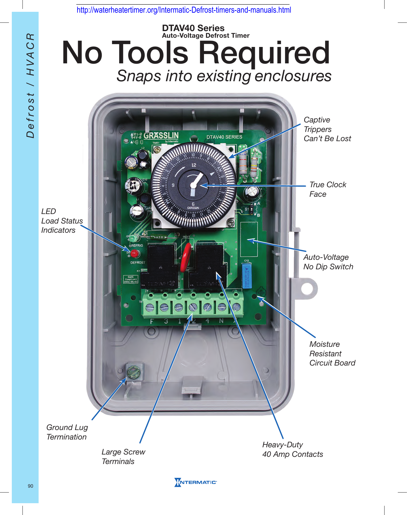
Grasslin Dtav40 Wiring Diagram For electric heat, hot gas or compressor shutdown defrost. The Grässlin DTAV40 Series Auto Voltage Defrost Timer is applicable to air defrost (compressor. Intermatic/Grässlin's Defrost controls just got even better! The DTAV40 defrost control automatically selects the appropriate voltage between Wiring Diagrams .

Staircase Timer Wiring Diagram - Using On Delay Timer And ...
Aviation History magazine is an authoritative, in-depth history of world aviation from its origins to the Space Age. Aviation History offers air enthusiasts the most detailed coverage of the history of manned flight, with action-packed stories and illustrations that put the reader in the cockpit with pilots and military (Army, Navy, and Marines) aviators to experience aviation’s greatest dramas.

True Freezer Wiring Diagram - T 49f Wiring Diagram ...
Grasslin 40a Defrost Timer Wiring Diagram - wiring diagram is a simplified usual pictorial representation of an electrical circuit. It shows the components of the circuit as simplified shapes, and the power and signal friends amongst the devices. A wiring diagram usually gives guidance approximately the relative direction and covenant of ...
Paragon 8145 20 Wiring Diagram
Those pesky timers can be a little fiddly if you're not familiar with them.This short video will show you how to set your Grasslin Segmental Timer [https://g...

To Grow (1970) // Virginia Churchill Bath (American, active c. 1970) United States, Illinois, Beecher
Grasslin IHT/T Manual. Download Manual of Grasslin GPT/T Timer for Free or View it Online on All-Guides.com. This version of Grasslin GPT/T Manual compatible with such list of devices, as: GPT/T, GPT/W, IHT/T, IHT/W. Brand: Grasslin. Category: Timer. Type: Manual. Model: Grasslin GPT/T , Grasslin GPT/W , Grasslin IHT/T , Grasslin IHT/W. Pages: 2.

person holding red metal frame
http://waterheatertimer.org/Intermatic-timers-and-manuals.html#Talento-400 Grässlin (UK) Ltd Tel ... CONNECT WIRING IN ACCORDANCE WITH WIRING DIAGRAM.
Good Quality Grasslin Defrost Timer Wiring Diagram - Buy ...
Backplate wiring: Example Wiring diagram The diagram shows wiring for a mains-operated load. The link between terminals 3 and 5 must be fitted by the installer. For low voltage switching connect 230V L & N to 5 & 4 resp. and switch circuit to 3 & 2. E 5 4 3 2 1 N L N L M~ Supply 3. Fix backplate to socket box. 4. Connect wiring in accordance ...

Grasslin Timer Wiring Diagram - Wiring Schema
17 Nov 2019 — Wired incorrectly need wiring diagram. I have baxi combi boiler genesis 80 and grasslin timer need to no what wires go were there are 4 wires coming out the ...Wiring of grasslin DTAV40 defrost for norlake nodel - Fixya14 Nov 2019Wiring diagram for grasslin defrost timer 08219056 - Fixya24 Dec 2012Wiring diagram for grasslin 24hour mechanical immersion timer9 Jul 2014SOLVED: How to wire a grasslin pool timer - Fixya12 Oct 2013More results from www.fixya.com

True Freezer Wiring Diagram - T 49f Wiring Diagram ...
True Freezer T 49f Wiring Diagram. Grasslin Defrost Timer (Freezer Units Only). 13 TRUE will not warranty any refrigerator that has been .. louvered grill, wiring diagram is positioned on the. wires) N=White (Neutral) X=Purple (defrost termination) This info obtained from sheet included with the Grasslin Timer for the True Freezer.
Grasslin Defrost Timer Wiring Diagram - Wiring Diagram
Grässlin Defrost Timers were designed specifically for OEM ... DTAV Series Common Wiring Diagrams & Enclosure/Mounting Dimensions 99.8 pages

How to wire DT 1440 timer
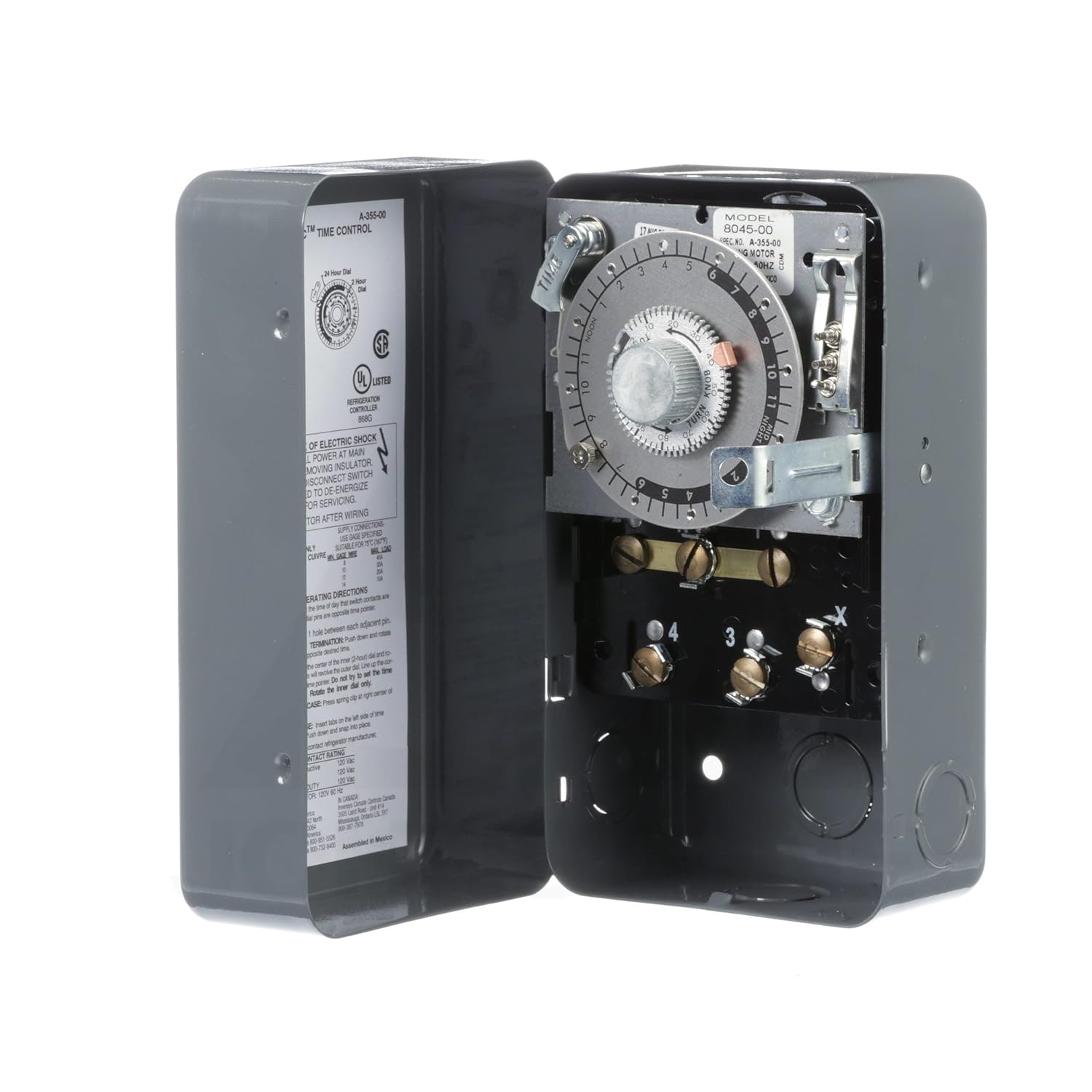
Determine model to be replaced (Grasslin or Competitors) from table below. ... DTMV40 Time/Time –Electric Defrost Wiring Diagram. 8045 Replacement.7 pages

TALENTO 211 - Grasslin - TALENTO211
Through the thousands of photos on the net concerning grasslin defrost timer wiring diagram, we all picks the very best selections having greatest resolution just for you all, and now this images is considered one of graphics selections in this greatest graphics gallery concerning Grasslin Defrost Timer Wiring Diagram.Lets hope you may enjoy it. ...

Grasslin Defrost Timer Wiring Diagram Collection
Grasslin Defrost Timer Wiring Diagram The Grässlin DTAV40 Series Auto Voltage Defrost Timer is applicable to air defrost (compressor shutdown) and electric or hot gas defrost systems where the . MODEL G Series Mechanical Defrost Timer. Installation Instructions. Figure 2. Snapping tabs off mechanism. Figure 3. Installing the G Defrost Timer.

Grasslin Timer Wiring Diagram - 36
Grasslin 010 0011a Wiring Diagram - wiring diagram is a simplified welcome pictorial representation of an electrical circuit. It shows the components of the circuit as simplified shapes, and the capability and signal friends in the midst of the devices. ICP Heil Tempstar HK61EA017 Heat Pump Defrost Control
Hvac Defrost Timer Wiring - Wiring Diagram
Grasslin Timer Wiring Diagram Free Download | Manual E-Books - Intermatic Pool Timer Wiring Diagram The diagram provides visual representation of an electric arrangement. However, the diagram is a simplified version of this structure. It makes the process of building circuit easier.

HELP, How To Wire Contactor For Switching HID Lights ...
Grasslin SW1 DT040 A DT140 A DTMVA DTSX A DTAV40 A/B per system Time Initiated & Time Terminated Paragon Precision SW1 8045 6045 8041 6041 A 8047 6047 B Time Initiated & Pressure Terminated 8245A 8247 B Time Initiated & Pressure or Temperature Terminated 8145 6145 8141 6141 A 8143 B Refrigeration Mode: Green light ON and Red light OFF (K1 NC ...

Grasslin Dtav40 Wiring Diagram
Grasslin Timer Wiring Diagram Grässlin UK Connect wiring in accordance with wiring diagram. Do not combine timer to control a load on a separate supply circuit, which can be a different. Wired incorrectly need wiring diagram. grasslin timer need to no what wires go were there are 4 wires coming out the timer red and brown together white and.

Old Timers, Elko, Nevada (1974) // Jonas Dovydenas American, born Lithuania 1939
Replacing a Grasslin time clock in your saltwater chlorinator? Here are the instructions on setting the clock. Grasslin time clocks are available from Direct...

Marina City: Finish Diagram (n.d.) // Bertrand Goldberg American, 1913-1997
Supco Heavy Duty 8 Hours 25 Minutes Refrigerator Tmdc Defrost Timer 825 1 China And Made In Com. Supco S8145 20 Complete Commercial Defrost Timer Replaces Paragon 8145 Canada. T 49f Wiring Diagram Swapping Timer On True T49f Freezer From Grasslin Dtsx Im 120tm To A Supco S814100 I Need Wirecolor.

grayscale photo of a woman
Pool pump timer bypass in 240v system intermatic wiring t104 off with heater delay circuit basic repair t104r won t turn on grasslin ground i have a sul181h electrical 7 days dual gpo hydroxypure Guidance Needed For Wiring Of Pool Pump Timer Bypass In 240v System Diy Home Improvement Forum Intermatic Pool Timer Wiring […]

Walk In Freezer Defrost Timer Wiring Diagram - Diagram For You

Grasslin Defrost Timer Wiring Diagram - Wiring Diagram And ...
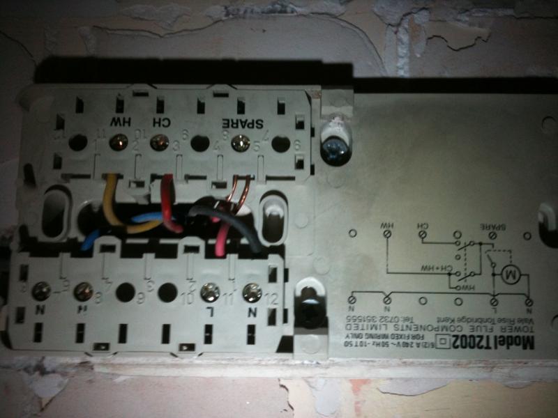
Replacing a Grasslin T2002 | DIYnot Forums

T-49f wiring diagram: Swapping timer on True T49F freezer ...

Grasslin Defrost Timer Dtsx B 240 Wiring Diagram - Wiring ...

Grasslin Defrost Timer Dtsx B 240 Wiring Diagram - Wiring ...

Intermatic Digital Timer Wiring Diagram - Wiring Diagram
Intermatic Timer Switch Wiring Diagram

Grasslin Pool Timer Wiring Diagram - Wiring Diagram
Grasslin Mechanical Timer Wiring Diagram - Wiring Diagram

Grasslin Dtav40 Wiring Diagram

Time Clock And Contactor Wiring Diagram - Complete Wiring ...
Supco Defrost Timer Wiring Diagram - Complete Wiring Schemas

SOLVED: How do i wire my diehl 880 ? - Fixya
0 Response to "36 grasslin timer wiring diagram"
Post a Comment