37 open center hydraulic valve diagram
348-9201-707 VA35 NPT Ports 3 Way 3 Position Air . With Power Beyond Main Relief 2500 PSI. Work Port Relief 2000. 14. Inlet DVA35-A440 348-9175-001 Relief Valve DVA35-MRV-2 391-1873-004 Avoid Using Tandem Center Valves in Series. Connecting Multiple Open Center Valves Using Power Beyond. Directional Control Valves - What Every Engineer Should Know. A Quick Guide to the Basics of Hydraulic Relief Valves and Filters. Valve Actuation. All positional valves need to be actuated to perform a function. We will start with mechanical ...
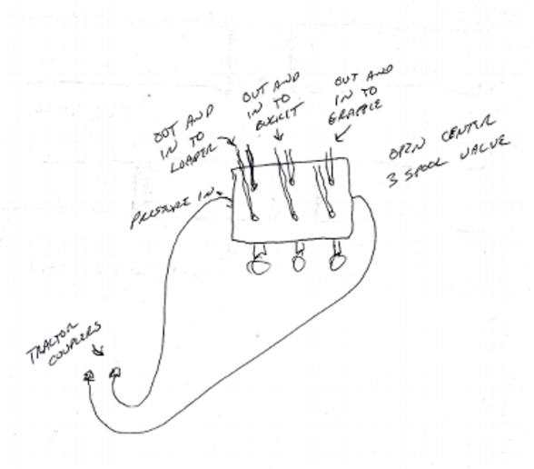
Open center or through center valves need to be connected in series using power beyond porting. Power Beyond allows unused flow to power multiple valve sets downstream. Power beyond also allows the designer to choose which valve sections are more important than another.

Open center hydraulic valve diagram
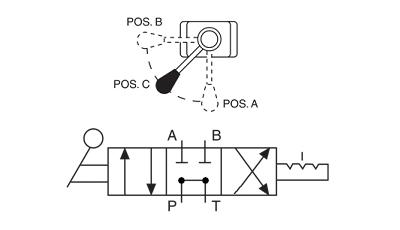
Hydraulic Kick-out Adjustment - The SH & SHA models have an adjustable single hydraulic kick out preset to 800-1000 psi. The HHA model comes equipped with a double hydraulic kick out preset to 800-1000 psi. To adjust kick-out pressure: Locate jam nut, and set screw on the spool action cap. (Opposite valve's handle) Positions. Most directional control valves are of a spool-type construction. The spool has lands and undercuts, housed within precision-machined casing. As the spool shifts, the lands and undercuts open and close flow paths. The example valve has 3 positions: center, straight through (P to A), and crossover (P to B). Exhibit 3 shows a simulation of the same analytical circuit with the system on standby but with the directional control valve switched to open center. Theoretical heat-load now is 1 kW (5.2 x 120 / 600), about a third of what it was with the pump sitting on its pressure compensator setting.
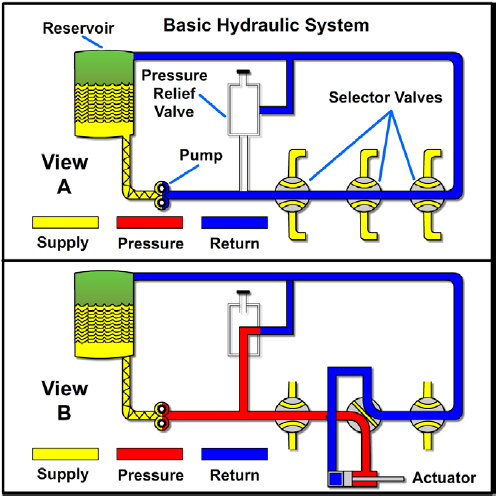
Open center hydraulic valve diagram. Power Valves USA D03 4 way 3 position hydraulic solenoid valves. Open center valves have all ports open to each other in the center position. Valve options are either DIN connector or wiring box electrical connections. Available in 12 volt DC, 24 volt DC, 120/60 volt AC or 240/60 volt AC. Pressure Relief Valve - Diagram , Working Introduction. Hydraulic energy is produced as long as the prime mover (usually an electric motor) drives the pump, and hydraulic pressure develops by resistance to pump flow.Hence, the hydraulic system suffers damage if the pump flow is not stopped or off loaded (recirculate) back to the tank during non-action periods of the circuit.Non-action ... Orbital Valve Information. Steering unit designs / options. The type of steering unit of greatest interest to Off-Road Vehicles is the Open Center / Non Load Reaction. It is the simplest and most economical design, has all the features we typically need, and uses a fixed displacement pump. Non-Load Reaction. An open center system is one having fluid flow, but no pressure in the system when the actuating mechanisms are idle. The pump circulates the fluid from the reservoir, through the selector valves, and back to the reservoir. [Figure 2] The open center system may employ any number of subsystems, with a selector valve for each subsystem.
Fluid power system diagrams require much more complex valve symbology than standard P&IDs due to the complicated valving used in fluid power systems. In a typical P&ID, a valve opens, closes, or throttles the process fluid, but is rarely required to route the process fluid in any complex manner (three- and four-way valves being the common ... Figure 2. Connection of an additional open center DCV using the power beyond facility. Most mobile directional control valves can be made closed center by plugging the drilling between the pressure and tank galleries and leaving the power beyond port plugged (Figure 3). This means that if the existing valve is closed center, supplying pump flow ... VES Valves PARALLEL HYDRAULIC CIRCUITS OUTLET CONVERSION PORT OPTIONS The most common type of hydraulic circuit is the par-allel circuit. Refer to the parallel circuit diagram. With all valve spools centered, the pump flow will return to tank at low pressure through the open center bypass. When a spool is actuated, the open center bypass is The terms open center and closed center are used to differentiate the two system designs as each describes the construction of the directional control valve as well as the type of hydraulic circuit being used within the system. With an open center system, flow is continuous and pressure is intermittent - which is contrary to a closed center ...
The CV432 open center valve is a parallel circuit valve which is designed to operate in open center hydraulic systems up to pressures of 320 bar (4600 psi) and flow rates of up to 80 l/min (21 USG pm). The LS version of the CV432 is designed to operate with a Fig 2 shows a simplified pump-powered system in which a control valve transmits pressure ... A schematic diagram for a transport aircraft hydraulic system is shown at Fig 3. The function ... fluid at low pressure at the open end of the stroke and expelling it at high pressure at the closed end, as shown in Fig 4. Parker offers a wide range of hydraulic valves for a variety of mobile and industrial applications. We manufacture all types of hydraulic valves: from directional control valves to pressure control, flow control, shuttle, sequence, high pressure non-return and ball valves, from monoblock and sectional to manifold mounted, in-line and slip-in cartridge valves, from standard on/off valves to ... Description. The 4-Way Directional Valve block represents a directional control valve with four ports and three positions, or flow paths. The ports connect to what in a typical model are a hydraulic pump (port P), a storage tank (port T), and a double-acting actuator (ports A and B).Fluid can flow from the pump to the actuator via path P-A or P-B and from the actuator to the tank via path A-T ...

Patent US4122867 - Hydraulic valve with open center ...
Hydraulic Directional Control, BA series valve is a 3-position, 4-way valve in 1,2 or 3 spool versions with float available. 12-volt solenoid 3-position, 4-way. For full functionality of this site it is necessary to enable JavaScript .
Basic Diagrams and Systems | Engineering Library
Hydraulic Spool Valve Diagram Introduction: E -Type Features: In the neutral position , all oil ports closed, not flow . Functional characteristics: 1. The inlet and outlet ports of device are closed, hydraulic actuator can be fixed in any its' working mechanism position, and no movement or rotary further even if there is external force on it ...

2 Spool Prince SV Sectional Control Valve Open Center w ...
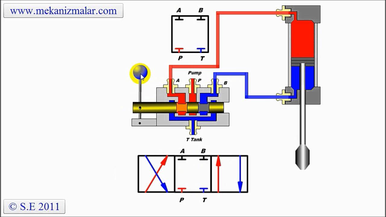
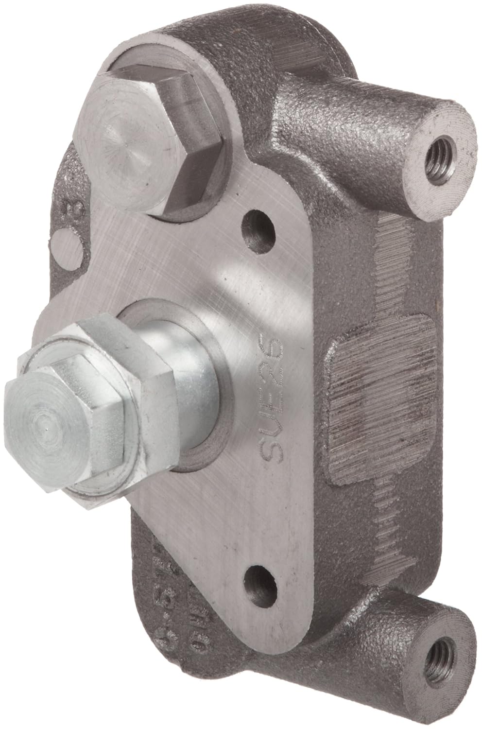
The image to the right shows a cutaway of an actual hydraulic control valve. The valve shown in the illustration is a open center valve, meaning that the oil flow is returned to the reservoir when the valve is in the neutral position. The spool valve has the capability to direct fluid flow to either end of the actuator.

9 SPOOL SV VALVE OPEN CENTER W/POWER BEYOND
Operation of the system following actuation of the component depends on the type of selector valve being used. Figure 12-5: Basic open-center hydraulic system. Several types of selector valves are used in conjunction with the open-center system. One type is both manually engaged and manually disengaged.

Directional valve Manually operated - miniBOOSTER ...
Hi this video explains about the open center hydraulic system.Hydraulic systems are of two types:1. Open center hydraulic system.2. Closed center hydraulic s...

Hydraulic Symbology 201 - industrial directional valves
Simple, compact and heavy duty designed monoblock valves from 1 to 6 sections for open and closed centre hydraulic systems. H Fitted with a main pressure relief valve and a load check valve. H Available with parallel or series circuit. H Optional carry--over port (only for parallel circuit). H Diameter 20 mm --0.79 in interchangeable spools.
Hydraulics, open-center, pressure compensated (PC) - 21.1 gpm
Hydraulic and Pneumatic Knowledge Fluid Power Equipment. Basic Hydraulic Open Center System Schematic. Open-Center System. In this system, a control-valve spool must be open in the center to allow pump flow to pass through the valve and return to the reservoir.

Open sign license plate
http://http://www.mekanizmalar.com/menu_pneumatic.htmlThis video explains the working principles of an open center spool valve.
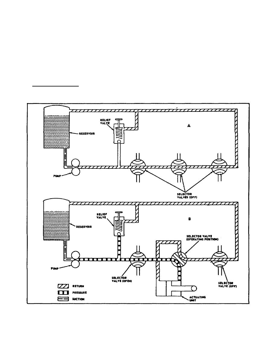
Figure 2-7. Basic Open-Center Hydraulic System.
look here. jd432 hydraulic system diagram - Google Search more info. " Summary The Power Beyond hydraulic system is used as a pressure/flow source for additional functions equipped with independent flow control valves. For example, planter vacuum motors, spray pumps, lift cylinders. Use Power-Beyond when: Tractor SCV control is not needed. Implement control valve requires external load sense ...
Closed Center Valve - YouTube
This option provides for conversion from open center to closed center by blocking the open center flow passage with the closed center plug as shown. It may be used in any standard Cross SA or BA valve featuring the conversion plug/power beyond machining in the BYD port. The valve may also be ordered already converted to closed center.

VALVE, HYDRAULIC DIRECTIONAL CONTROL DOUBLE OPEN CENTER ...
Hydraulic valves have a tendency to be the most complex components of a hydraulic system, and their schematic symbols are just as complex. ... A 4 port, 3 position, pilot operated, spring returned, open center valve A relief valve A 3 port, 2 position, pilot operated, spring returned valve A 3 port, 2 position, solenoid operated, spring ...

Schematic diagram a) components of hydraulic steering ...
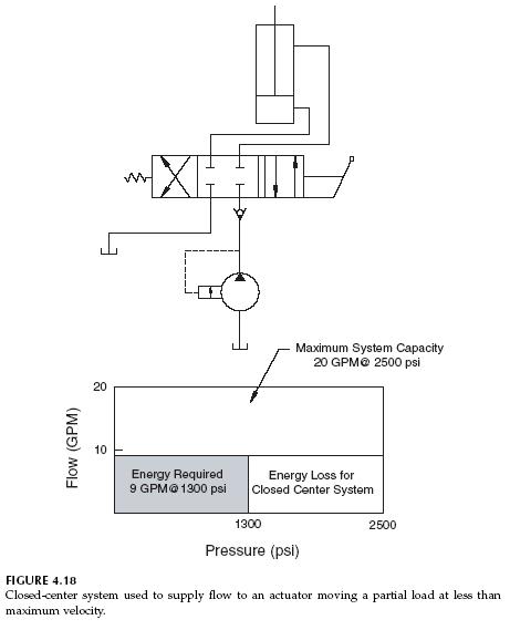
Exhibit 3 shows a simulation of the same analytical circuit with the system on standby but with the directional control valve switched to open center. Theoretical heat-load now is 1 kW (5.2 x 120 / 600), about a third of what it was with the pump sitting on its pressure compensator setting.

1590 - DRILL, GRAIN OPEN/CLOSED CENTER HYDRAULIC KIT EPC ...
Positions. Most directional control valves are of a spool-type construction. The spool has lands and undercuts, housed within precision-machined casing. As the spool shifts, the lands and undercuts open and close flow paths. The example valve has 3 positions: center, straight through (P to A), and crossover (P to B).
Hydrotools, Hydrotools, 4-Way, 3-Position (Open Center) Manual
Hydraulic Kick-out Adjustment - The SH & SHA models have an adjustable single hydraulic kick out preset to 800-1000 psi. The HHA model comes equipped with a double hydraulic kick out preset to 800-1000 psi. To adjust kick-out pressure: Locate jam nut, and set screw on the spool action cap. (Opposite valve's handle)

A look up shot of the world trade centre on a dreary rainy day in NYC.

A schematic of the steering system showing, both the open ...
Hydraulic Closed-Center Circuit | Hydraulic Valve

Hydraulic Closed-Center System | Hydraulic Valve
Prince SVE26 Directional Control Valve Open Center Outlet ...

5 Spool Prince SV Sectional Control Valve Open Center w ...

Molino Argentino, Oprn Door, Argentina

455 - DRILL, GRAIN Open/Closed Center Hydraulic Kit ...

How to configure mobile hydraulic valves using power beyond

Hydraulic Equipment Slowdown - Nailing Internal Leakage
Open Center Hydraulic question - Yesterday's Tractors

Prince Auto Cycle Valve With Power Beyond Option Available ...

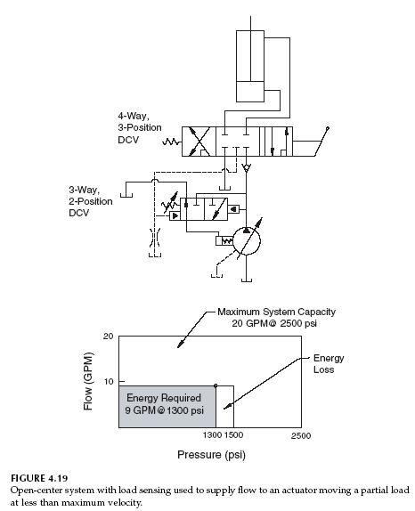
4 The pump in open-centre load sensing systems is ...

Hydraulic Circuits: Open Center Circuit | Hydraulic ...

Hydraulic Open-Center System | Hydraulic Valve

3 SPOOL SV VALVE OPEN CENTER
way: 4 Way Solenoid Valve Schematic
Figure 11.71 ISO Valve Symbols

Your dreams are next door

Hydraulic Open-Center System | Hydraulic Valve

Closed Center Versus Open Center Hydraulics | Brendan ...

Hydraulic Rotary Diverter Valve, 4 Way, Open Center, 24 ...

ãƒã‚¤ãƒ¤ãƒªãƒ†ã‚£ãƒ•ãƒªãƒ¼Open Center Selector Valve - マインクラフト画åƒ
0 Response to "37 open center hydraulic valve diagram"
Post a Comment