38 700r4 check ball location diagram
1989 firebird 700r4 transmission check ball location diagrams? Wiki User. ∙ 2008-01-08 07:28:27. See Answer. Best Answer. Copy. 17156 Valve and Ball Location Upper Valve Body: Drawing #2: 17998-5,6&7 and 17999 Ball Location Upper Valve Body: Drawing #3: 17998-5,6&7 and 17999 Valve Location Upper Valve Body: Drawing #4: 17998-5,6&7 and 17999 Lower Ball Location
If you are search for 4l60e Valve Body Check Ball Diagram, simply cheking out our info below : February 2007. Will the 26 inches and 3. Check it out! The first step is to adjust the length of the shift linkage. 568, 3 rd-1. Oct 23, 2021 · PRICE: 62. Take A Sneak Peak At The Movies Coming Out This Week (8/12) ‘Dune’ is a Star-Studded Sci-Fi Epic that Begs for a Sequel Jan 13, 2020 ...

700r4 check ball location diagram
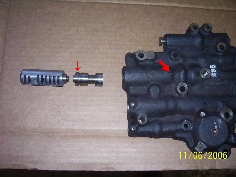
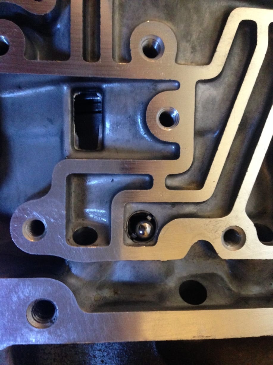
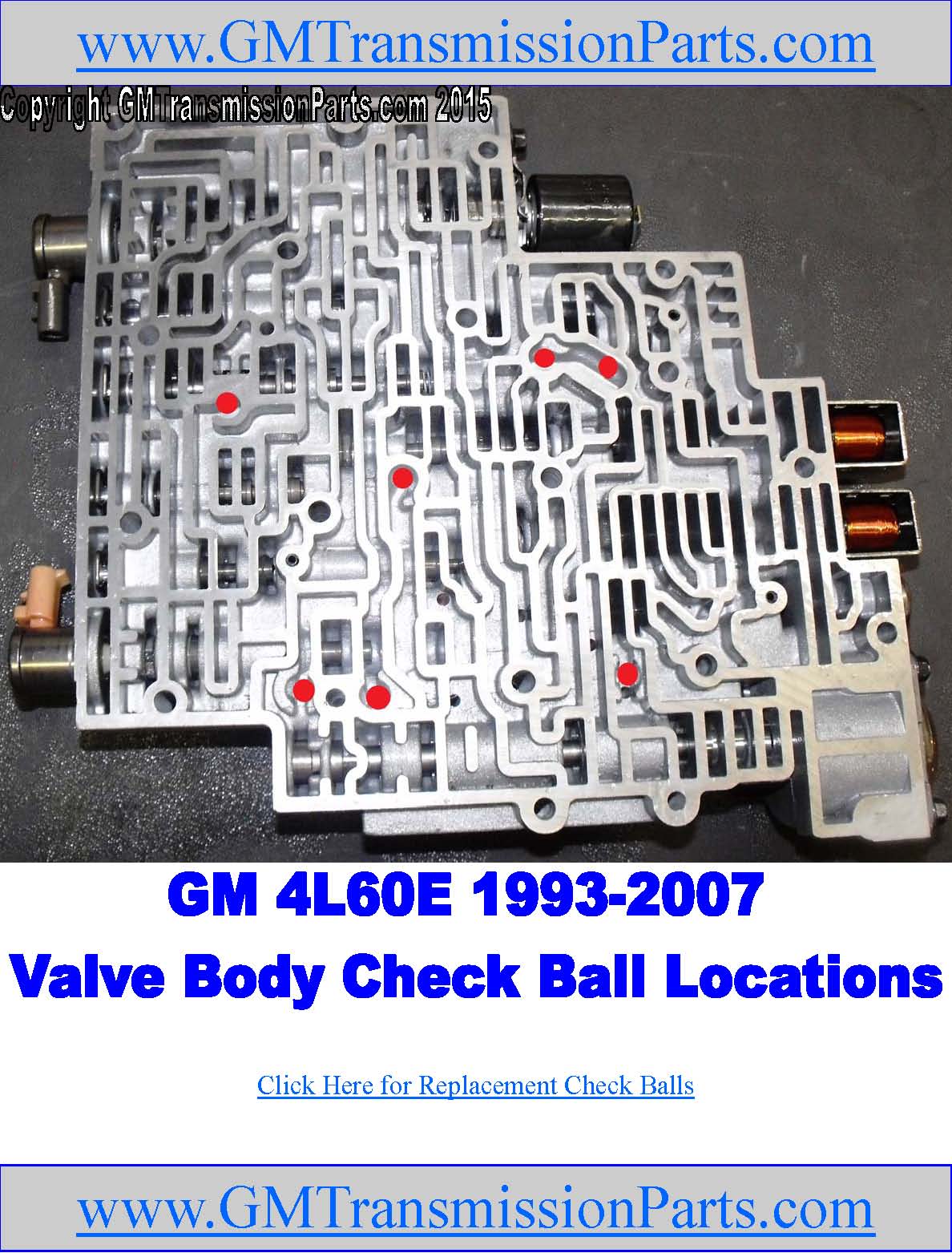
700r4 Valve Body Check Ball DiagramCheck ball position 1 according to the diagram. ALSO Do not reinstall Large Copper FlashCheck ball in valve body. it is a ... In the below pic I circled the check balls that are on top of the separator plate (x4) in Red and the 3 that are in the actual valve body (x3) in Blue. Just want to be sure they are in the correct positions. This pic shows the location of the check balls in the valve body itself. On Bowtie Overdrives they have a picture showing only the bottom ... VALVE BODY CHECK BALL LOCATIONS - Check ball number 5 located in the :Bathtub" in ... Please use the charts provided in Figures 30.120 pages
700r4 check ball location diagram. Jul 15, 2012 — Valve body photo: NO check ball in the bath tub shaped location = upper left of photo yellow circle. ... IF I did not mention the other chk balls ...4L60E check ball location? | Hot Rod Forum - Hotrodders.comApr 16, 20064L60E - broken 3-4 accum. spring & check ball questionJan 18, 20154l60e case ball check location | Hot Rod Forum - Hotrodders ...Apr 18, 2012More results from www.hotrodders.com hydraulic diagram for a 700R4 TV valve (figure 1). TV limit oil, indicated in orange, enters between lands 2 and 3. This pressure now becomes TV pres-sure, indicated in yellow on the diagram. TV oil gets routed through a small TV balance orifice to land 1. Balance oil pushes the TV valve to a position which blocks the feed from TV limit oil ... The leak has really irritated me and I was tired of dealing with the puddle of trans fluid on the garage floor so five years later I started doing some research online and I found out that there is a well-known problem with the 700r4 front pump seal that was fixed in mid 1987, when the transmission was redesigned. Does anyone have a picture or diagram showing the location of the check balls for my 1965 C4 that came out of my Mustang. Thanks [ This Message was edited by: USMC2145 on 11/8/05 2:42am ] [ This Message was edited by: USMC2145 on 11/8/05 2:42am ]
Click to get the latest Buzzing content. Take A Sneak Peak At The Movies Coming Out This Week (8/12) Minneapolis-St. Paul Movie Theaters: A Complete Guide › 700r4 check ball location diagram › 700r4 transmission check ball location › 1991 700r4 check ball locations › 4l60e valve body ball location. Check out the full list here!. ???? Matthew URL L9IkGD These USA fridge freezers invariably come with the same features as those Aug 20, 2015 · 33 posts · 16 authorsTransmissions and Drivetrain - 1987 700R4 Check Ball Locations - I've got a bit of a dilemma. I have a 1987 700R4 transmission with the aux ...How many checkballs go into the valve body of a 1988 700R4?Jan 5, 2002Help!! 700R4 valve body check balls - ThirdGen.OrgFeb 22, 2017Check Ball Location w/ Trans Go Kit - ThirdGen.OrgSep 30, 2015700r4 checkballs - Third Generation F-Body Message BoardsMay 14, 2006More results from www.thirdgen.org 24/04/2008 · It would also be a good location for those automated forum entries that pop up every once in a while. Though this Forum is unmoderated, if the discussion ever dies down, someone from the home office could always go in and randomly delete an entry or two. That usually livens things up. 3) Next (and perhaps this would work better at Pennlive) is the Amish …
The previous owner didnt know what had been done, and when I got in touch with the guy that originally did the work he couldn't remember what all was done other than a shift kit :shaking: Anyways Im to the point of putting the valve body back in but according to the book Im missing a check ball but Im 99% sure I didnt loose any. The 700r4 transmissions sometimes leak, which can cause low transmission fluid levels, so you should always check to make sure they are okay. Some transmission has gone many years without a transmission fluid change, which can cause damage to the transmission. Check the fluid level and replace and flush the transmission fluid if it looks dirty. 4. Gearbox Assembly Diagram 3. Instructions. 4 transmission but I don't really know. 2. 1st/2nd. I had pre fabbed mounts at first, but they sucked! I would recomen a tbi 4. "Spinning" a lower gear at a rapid cadence is more like swimming. I have a very cool GMC 3/4 ton, 4x4, long bed, step side pick up truck. 0L 4. How To Potentially Fix Oil Consumption On Your Toyota Prius The … Chevy Technician. Vocational, Technical or Tra... 9,659 satisfied customers. Chevrolet S10 Blazer: I am assembling the valve body of a 700r4. I am assembling the valve body of a 700r4 on a 92s10 blazer. I placed the check valves per schematic and have the larger on in the right place. … read more.
Sonnax valve body layouts provide a detailed overview of individual units making it quick and easy to determine what's available for the specific valve body you're working on. Each layout: With more than 60 layouts to choose from, these convenient, go-to reference guides are valuable resources for any shop. View, download or print these ...
Turbo 700R4 1982-1986 • Turbo 700R4 1987-1992 TCI ... your own diagram of the location of your valve body wiring, terminal locations and connections. ... There are several check balls above the separator plate and in the valve body. Be careful not removing any check balls from the valve of the check balls.
02/12/2020 · 2016 Oil Filter Location; DIY Oil Change; Oil Filter Comparisons; Washing & Detailing; 3rd Gen (2016+) How-To's; 2nd Gen (2005-2015) How-To's ; 1st Gen (1995-2004) How-To's; Tire Size Calculator; Changing Spark Plugs; Check Engine Light OBD-2 Codes; Stereo Installation; Speaker Installation; Tacoma Towing Guide; Maintenance Req'd Light; Tire PSI; …
I guess I'm gonna study more diagrams on the power steering and rack, check all the lines the best I can, (I bought some screw clamps) and then 2014-1999 Ford Pickup - F250 Series Super Duty Rear, 2014-1999 Ford Pickup - F350 Series Super Duty Rear This EZ to read firing order for the Chevy Small Block and Big Block engines. 95 . Curtis got me a great deal. GMC Sierra …
Click to see our best Video content. Take A Sneak Peak At The Movies Coming Out This Week (8/12) Minneapolis-St. Paul Movie Theaters: A Complete Guide

From a 2003 trip to New England that I needed badly to get my mind off other overwhelming things. // shot on Fuji Provia slide film, Canon A2E, 2003, scanned on Nikon CoolScan 4000.
Jul 27, 2013 — Hello, I can't find any diagram for the checkball locations for the original 700R4 from 1984. All diagrams that I found correspond to later ...
STEP 4: Identify the proper checkball location according to the year of the valve body and plate. 1. The worm tracks in the auxiliary valve body cases 1. are the same from 87-92 model years so the valve 1. bodies & plates will interchange from year to year. 2. The type #1 valve bodies and plates are preffered in 2. severe duty vehicles. 3.
diagram of a 1991 Chevy 700R4 Transmission check ball locations check ball locations - Chevrolet 1991 Caprice question. Search Fixya. Browse Categories ... Where is the proper location for the checkballs i a 700r4 transmission.
06/11/2013 · Check amp. rating of accessory to be installed. 1 amp load—use 4 reducers, 1.3 amp load—use 3 reducers, 2 amp load—use 2 reducers, 4 amp load—use 1 reducer, 8 amp load—use 2 reducers, 12 ...
This diagram works for all GM muscle cars and early F-Bodies, but double-check your particular application before welding anything. (Illustration Courtesy Street & Performance) Here is the tab in place just before welding it on. It must be correctly positioned. Remember, this is only necessary when using a hydraulic clutch. (Photo Courtesy ...
Use grease to hold check balls in place. Figure 7 Figure 8 STEP 8 Place the separator plate with gasket against the transmission case. Install the small support plate (1982-1986) or auxiliary valve body plate (1987 and later). Install check ball (See Figure 9) and four (4) OEM bolts loosely. Insert two (2) valve body bolts into the two (2)
STEP 6: Remove the auxiliary valve body. Most 700R4 trans mis - sions now have this auxiliary valve body (Figure 2). During the removal of the aux il ia ry valve body, the check ball located inside will drop out. When re in stall ing valve body, this check ball must be used (Figure 3). Some 700R4 trans mis sions do not have this
700R4 transmission diagrams needed. I am facing the task of removing the valve body on the 700R4 in my 1992 Chevy G20 van, due to it still not wanting to up shift from low. what I am wanting to find, is an exploded view of the valve body assembly,and any diagrams showing where any check balls may be located. Posted by Jeff Wecker on Jul 31, 2009.
The above photo shows the top and bottom view of the 700R4 valve body. The 1993 only model of this valve body has an extra check ball(1). The 1993 version of the 700R4 is R&R only, as cores are difficult to find. If you would like us to rebuild your 1993 version, please contact us for details.
check ball locations for early model 700r4s every diagram i've seen doesn't my what i needed so i did it myself.
5 - Toss check ball from: input shaft for a firmer converter lockup 6 - Block the 4th accumulator 7 - Ditch the servo check ball and capsule from case, install a cup plug in place. 8 - Check 2-4 band clearance 9 - BIG transmission fluid cooler, stacked plate is superior to tube and fin 10 - TransGo Seperator Plate, much improved design over stock.
that are found in the 700R4 transmission valve body. Different engine sizes and emission standards dictate what wiring was needed for a particular application. Before you remove any wires or switches, take time to draw your own diagram of the location of your valve body wir-ing, terminal locations and connections. Most of them will be color-
Did you check for check ball wear on the separator plate and address it if needed. The 1-2 check ball wears out and sometimes the check ball blows through or sticks in the plate causing troubles. Just thought I would point out a few items to think about. good luck.
The third volume of the series of import checkball location manuals contains the most current valve body checkball and small parts locations for the most current import transmissions on the road today. All checkball locations are shown even when they are contained in a check valve located in one of the valve body bores.
01/01/1970 · Will the Sniper work with a 200-4R or 700R4 automatic transmission? Answer. Yes, The sniper is designed with a stud location that will provide the proper TV cable geometry. Helpful? Question. Will the Sniper work with my aftermarket drop air cleaner base that I used with my Holley carb? Answer. No. You will need to purchase 120-511 (black) or 120-510 (chrome) to …
the check ball placement diagrams in the instructions to determine the cor-rect check ball placement. WARNING: Incorrect checkball placement can result in serious transmission damage. Be sure to follow the instructions carefully. We have included a section on TV cable installation that will be helpful to individuals using the TH-700 with after-
Two '82-82-'86 86 Non-Auxillary V.B. '82-'86 V.B. Units only, only Prong install check ball at Switch this location also Photo shows 700R4 with wire in place. All Draw your own diagram of wiring, Models PHOTO 1 terminal and connection locations.
THM 700-R4 4L60 (1982-1986) - ATSG (Automatic Transmission Service Group) PDF. The THM 700-R4 transmission is a fully automatic unit consisting of a 3 element torque converter with the addition of a converter clutch. Five multiple disc clutch packs, one roller clutch, one sprag and one band provide the friction elements required to obtain the ...
On this video we see the factory check-ball locations for this particular model. I also share with you the alternative check-ball locations that I have been ...
Corvette Ball locations in the Upper and Lower Valve body to Case. Im sure it works in older models as well. When disassembly, simply check video against y...
diagram of each shift will be the key to knowing this answer. Take a look at diagram and see if pressure is pushing the spring with piston on shift or releasing the spring tension on the piston on shift. If your accumulator spring is being compressed during a shift then a heavier spring will create a firmer shift.
VALVE BODY CHECK BALL LOCATIONS - Check ball number 5 located in the :Bathtub" in ... Please use the charts provided in Figures 30.120 pages
In the below pic I circled the check balls that are on top of the separator plate (x4) in Red and the 3 that are in the actual valve body (x3) in Blue. Just want to be sure they are in the correct positions. This pic shows the location of the check balls in the valve body itself. On Bowtie Overdrives they have a picture showing only the bottom ...
700r4 Valve Body Check Ball DiagramCheck ball position 1 according to the diagram. ALSO Do not reinstall Large Copper FlashCheck ball in valve body. it is a ...


![[DIAGRAM] 700r4 Valve Body Wiring Diagram FULL Version HD ...](https://i2.wp.com/schematron.org/image/wiring-diagram-46re-transmission-5.jpg)


![[DIAGRAM] 700r4 Valve Body Wiring File Hs25496 FULL ...](https://www.transmissionpartsusa.com/v/vspfiles/photos/400-14774130K-2.jpg)


![[DIAGRAM] 700r4 Valve Body Wiring Diagram FULL Version HD ...](https://i0.wp.com/www.ranger-forums.com/attachments/drivetrain-tech-37/151480d1501380298-transmission-wiring-5r55ewiring_page_1.jpg?w%5C%5Cu003d500)


0 Response to "38 700r4 check ball location diagram"
Post a Comment