38 yamaha 703 remote control wiring diagram
This remote control box has designed that both shift and throttle control can be actuated by operating the remote control lever. For the correct operation ... Yamaha 703 Remote Control Wiring Diagram – yamaha 703 remote control wiring diagram, Every electrical structure is composed of various unique pieces. Each component should be set and linked to other parts in particular manner. If not, the arrangement won’t function as it should be.
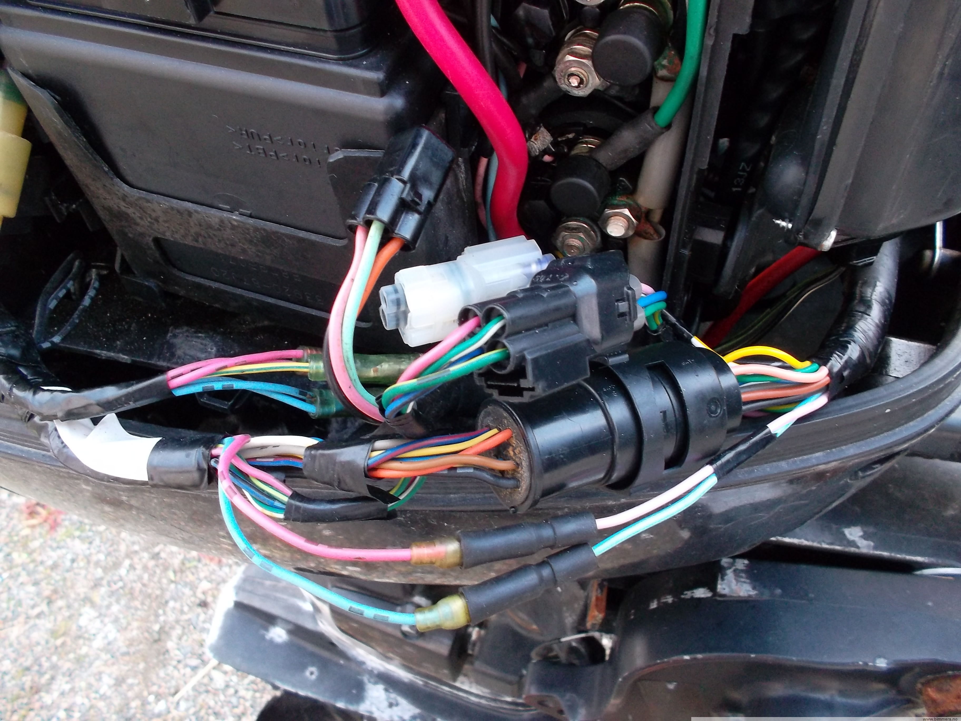
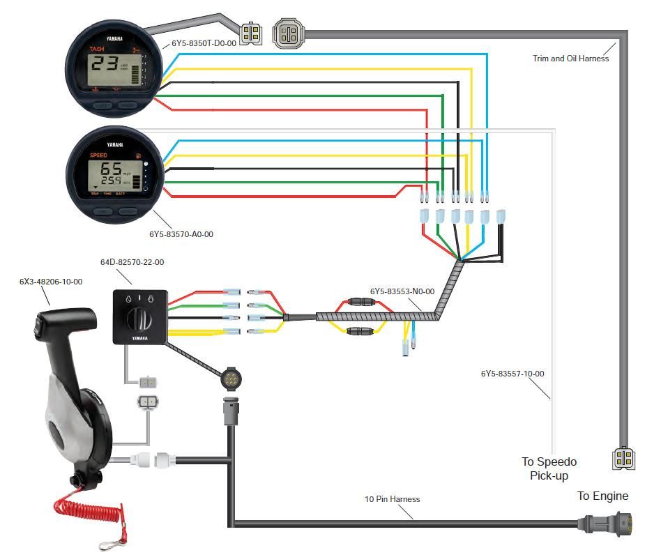
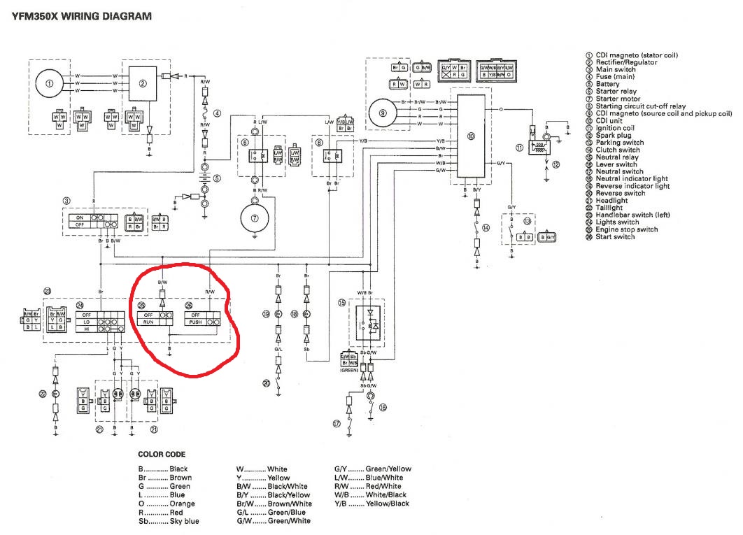
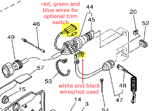
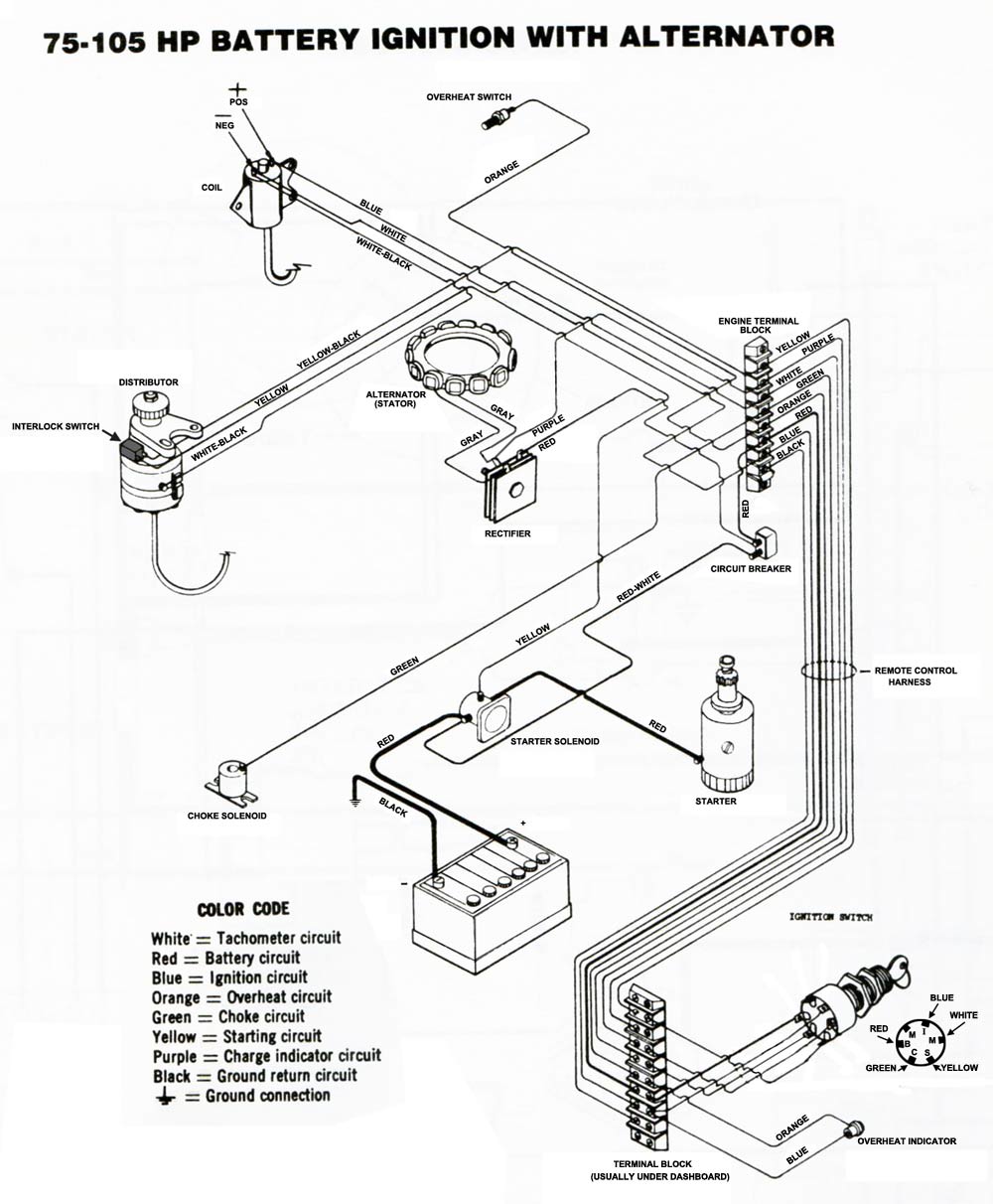
yamaha remote control wiring diagram – Use wiring diagrams to help in building or manufacturing the circuit or computer. They are also useful for making repairs. There are 4 individual wires coming out of Yamaha's control box, terminated with bullet connectors. Colors of the wires are red, green, yellow, and black.
Yamaha 703 remote control wiring diagram
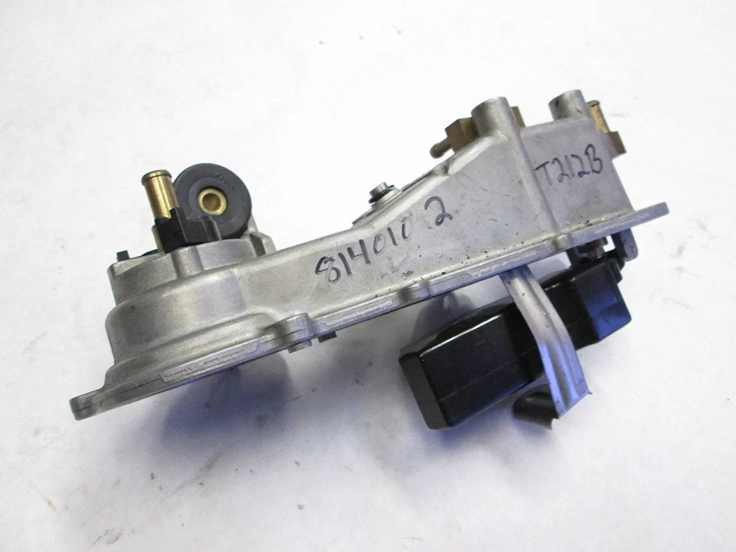
A 703 Side Control came with a Yamaha outboard engine I bought recently. I am surprised there is no rubber or similar gasket to go between it and the mounting surface. In my case, I am using a supplied spacer and would have thought there should have been one to go between that and the side control. Re: Yamaha 703 remote control wiring diagram usually 4 wires from that box. yellow is ignition supply to guages, green is tach signal, red is constant 12v for digital speedo memory (wont turn on without it), black is ground. some boxs have no red wire. Yamaha 703 Control Converting Pull To Push. Linkedin l30cm 10 pin 703 yamaha outboard remote wiring diagram manual for control to helm the box ribnet genuine conrol whaleflo premium need help relocating side rigging 1994 1996 motors steering system 48205 a0 00 mount 2022 f70 la needed on a 7 harness can you tell trim tilt switch assy 150 175 200 converting pull push problem page 2 user 2015 ...
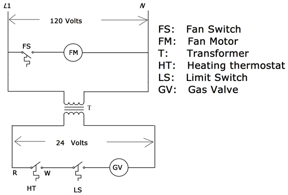
Yamaha 703 remote control wiring diagram. Yamaha 703 Instructions Manual. Side mount remote control. Hide thumbs. Also See for 703: Operation manual (20 pages) 1. Table Of Contents. 2. Mar 12, 2018 - Wiring diagram yamaha 703 remote control Guide to Image Wiring ... yamaha outboard remote control comp parts 703 diagram and parts Car Chloe ... 06-14-2018, 03:10 PM. Damn if I can find out where the pink, black and yellow wires are to go. There is a buzzer inside the 703 to which the pink wire and the yellow wire are connected. Yellow provides voltage to the buzzer when the key is on. The engine provides a ground via the pink wire to cause the buzzer to sound. 703 Yamaha Remote Control Wiring Diagram 13.05.2019 13.05.2019 0 Comments on 703 Yamaha Remote Control Wiring Diagram There are 4 individual wires coming out of Yamaha's control box, You can also find the wiring diagram for the yamaha control box in this.
10 Aug 2012 — I have searched but come up with very little. I have a Yamaha 703 control box hooked up to a Yamaha 85HP outboard. (no manual for the 703). yamaha 703 remote control wiring diagram – You will need an extensive, professional, and easy to know Wiring Diagram. With this kind of an illustrative guide, you’ll have the ability to troubleshoot, avoid, and complete your projects easily. Yamaha 703 Remote Control Wiring Diagram. Variety of yamaha 703 remote control wiring diagram. A wiring diagram is a simplified traditional pictorial depiction of an electrical circuit. It shows the elements of the circuit as simplified shapes, as well as the power and signal connections in between the devices. A wiring diagram generally gives info concerning… 11 Apr 2020 — Hi... I trying to find a wiring diagram/installation manual for a Yamaha 703 Remote. Can anyone help with finding a manual to download ...
Yamaha 703 Control Converting Pull To Push. Linkedin l30cm 10 pin 703 yamaha outboard remote wiring diagram manual for control to helm the box ribnet genuine conrol whaleflo premium need help relocating side rigging 1994 1996 motors steering system 48205 a0 00 mount 2022 f70 la needed on a 7 harness can you tell trim tilt switch assy 150 175 200 converting pull push problem page 2 user 2015 ... Re: Yamaha 703 remote control wiring diagram usually 4 wires from that box. yellow is ignition supply to guages, green is tach signal, red is constant 12v for digital speedo memory (wont turn on without it), black is ground. some boxs have no red wire. A 703 Side Control came with a Yamaha outboard engine I bought recently. I am surprised there is no rubber or similar gasket to go between it and the mounting surface. In my case, I am using a supplied spacer and would have thought there should have been one to go between that and the side control.
Yamaha Control Box 703/704 Neutral Switch - The Hull Truth ...

2014 Yamaha 150 Hp Trim Wiring Diagram - Outboard Engine ...

Delightful Readings: Troubleshooting OBM (Out board motor).
Yamaha 703 Remote Control Wiring Diagram

Yamaha Outboard Electrical Wiring Diagram - Yamaha 703 ...
Yamaha Outboard Tachometer Wiring Diagram | Wiring Diagram
Yamaha Trim Gauge Wiring Diagram - Wiring View and ...
Yamaha Outboard Analog Tachometer Wiring Diagram - Style ...
Yamaha Control Box Wiring Diagram : Amazon Com Remote ...

Electrical Wiring Yamaha Outboard Wiring Diagram Pdf ...

Wiring Diagram For Yamaha Warrior 1700 / Https Encrypted ...

yamaha outboard remote control comp parts 703 diagram and ...

Yamaha 703 Remote Control Box Wiring Diagram
Cheap Mercury Outboard Ignition Switch Wiring Diagram ...

Yamaha Outboard Gauge Wiring Diagram - Wiring View and ...
Wiring Diagram For Yamaha Warrior 1700 - Wiring Diagram ...

This home’s interior, though beautiful, houses a potential hazard on many levels, therefore, special care need be taken in order to safely operate this wood-burning stove, for not only does it generate a terrific amount of heat, it does so using flame, rather than electricity, which is much more difficult to control. This woman was about to place what appears to be a piece or treated lumber into the stove as fuel.
20 Boat Throttle Control Box Diagram - Wiring Diagram Niche
![[VS_5138] 703 Remote Control Wiring Diagram Free Diagram](https://static-cdn.imageservice.cloud/142573/30-hp-yamaha-outboard-wiring-wiring-diagram.jpg)
[VS_5138] 703 Remote Control Wiring Diagram Free Diagram

Yamaha Outboard Electrical Wiring Diagram / Yamaha ...

2014 Yamaha 150 Hp Trim Wiring Diagram / The motor has a ...

Yamaha Outboard Gauge Wiring Diagram - Wiring View and ...
703 Yamaha Remote Control Wiring Diagram Collection

Yamaha 704 Remote Control Wiring Diagram - Wiring Diagram
Yamaha 703 Remote Control Box Wiring Diagram

Yamaha Control Box Wiring Diagram : Amazon Com Remote ...

Yamaha Outboard Remote Control Wiring Diagram Fresh 2018 ...
Need help Relocating Yamaha 703 Side Mount Control Box ...

This home’s interior, though beautiful, houses a potential hazard on many levels, therefore, special care need be taken in order to safely operate this wood-burning stove, for not only does it generate a terrific amount of heat, it does so using flame, rather than electricity, which is much more difficult to control. This man was about to place what appears to be a piece or treated lumber into the stove as fuel.
Yamaha Outboard Electrical Wiring Diagram : Bbaeecc 40 Hp ...

Yamaha 292 Wiring Diagram / Yamaha Motorcycle Wiring ...
Yamaha Outboard Electrical Wiring Diagram : Yamaha Wiring ...

Yamaha Guitar Wiring Diagram - 2 Pickup Guitar Wiring ...

just got my new toy let's enjoy Netflix!!!

Yamaha 703 Remote Control Wiring Diagram - Yamaha 703 ...
Yamaha Outboard Control Wiring - Wiring Diagram Schemas

Yamaha Control Box Wiring Diagram - Wiring Diagram Schemas

Electrical Wiring Yamaha Outboard Wiring Diagram Pdf ...
0 Response to "38 yamaha 703 remote control wiring diagram"
Post a Comment