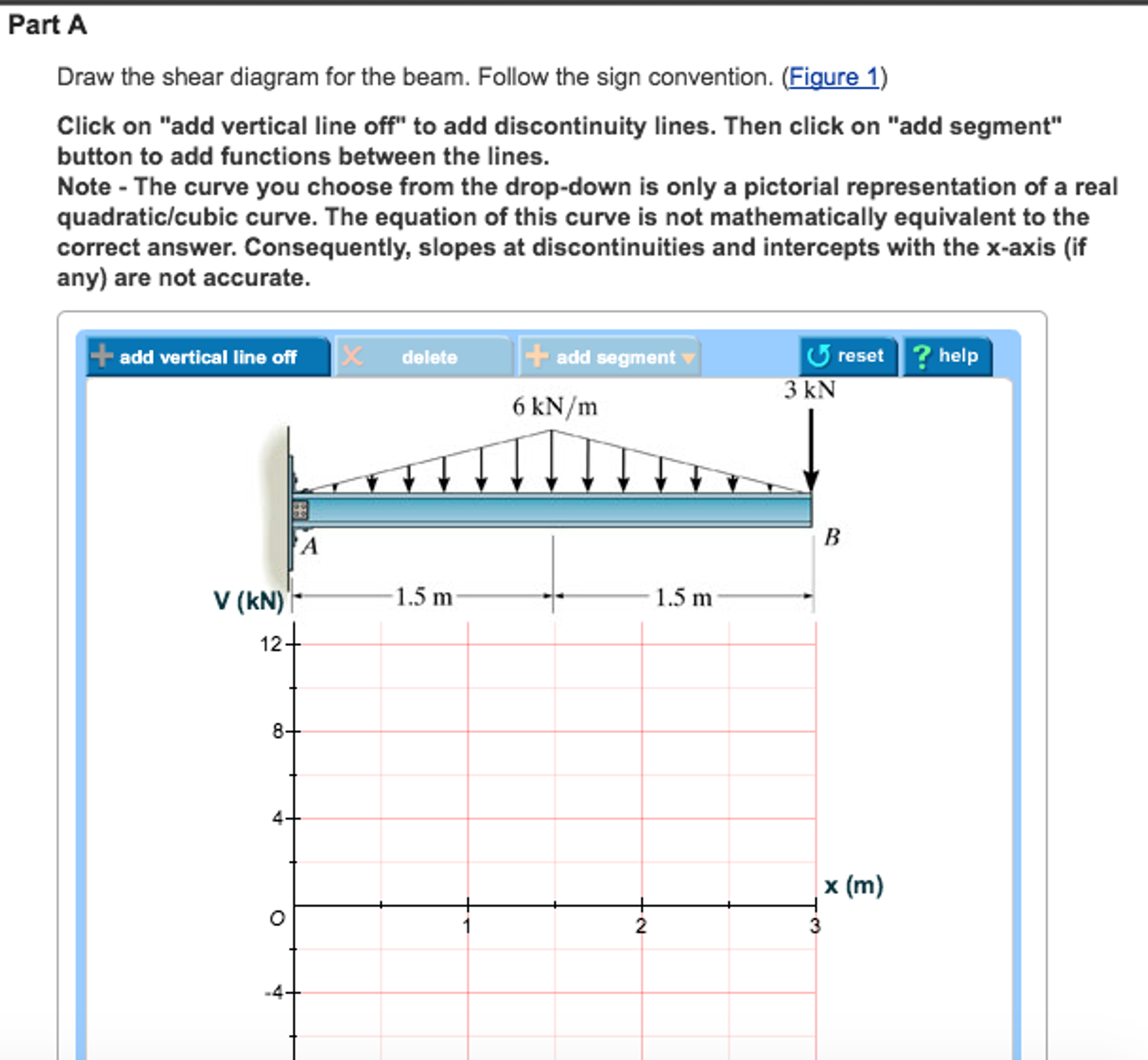
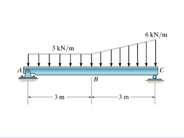
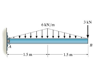
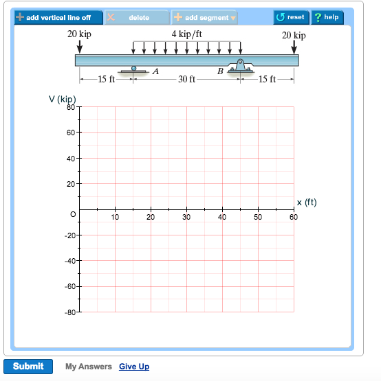
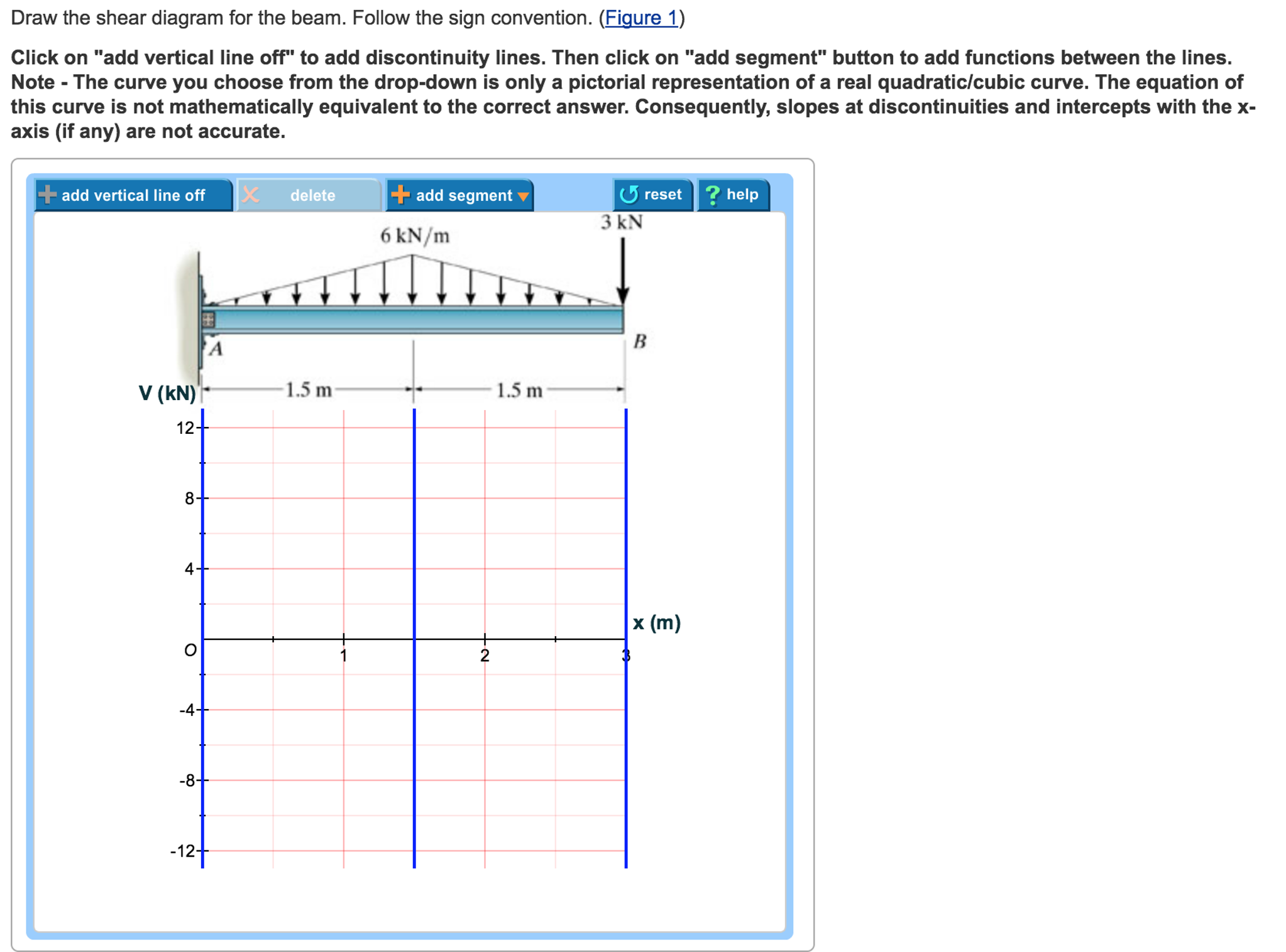
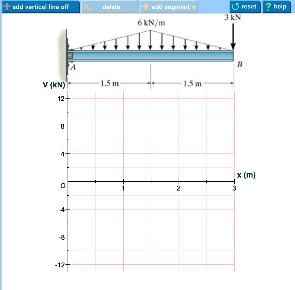
39 draw the shear diagram for the beam. follow the sign convention.
Solved march 30 2018 convention. Problem 789 from engineering mechanics statics 14th edition draw the shear and moment diagrams for... Sign Conventions. To calculate the shear forces of a beam, follow the following simple steps (as hand calculated by SkyCiv Beam Software). Calculating Shear Force Diagram - Step 2: Keep moving across the beam, stopping at every load that acts on the beam.
Follow the sign convention. Want to check out this answer and also more? Experts space waiting 24/7 to provide step-by-step solutions in as A: The drawing commands normally the strings of message that to produce a bigger string the graphical instru... Q: When the width of soil dimension...
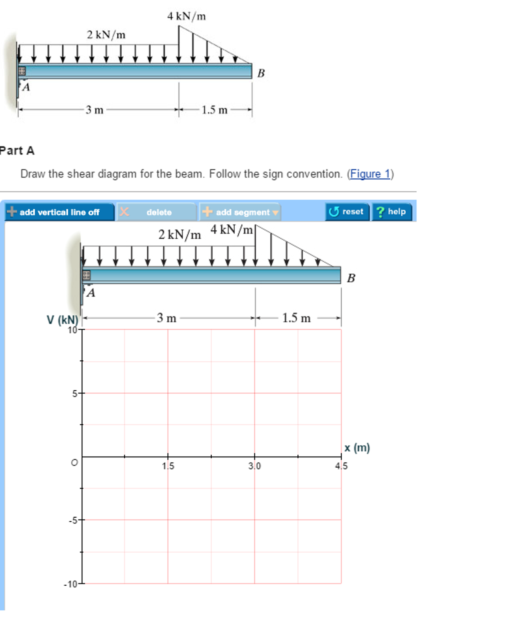
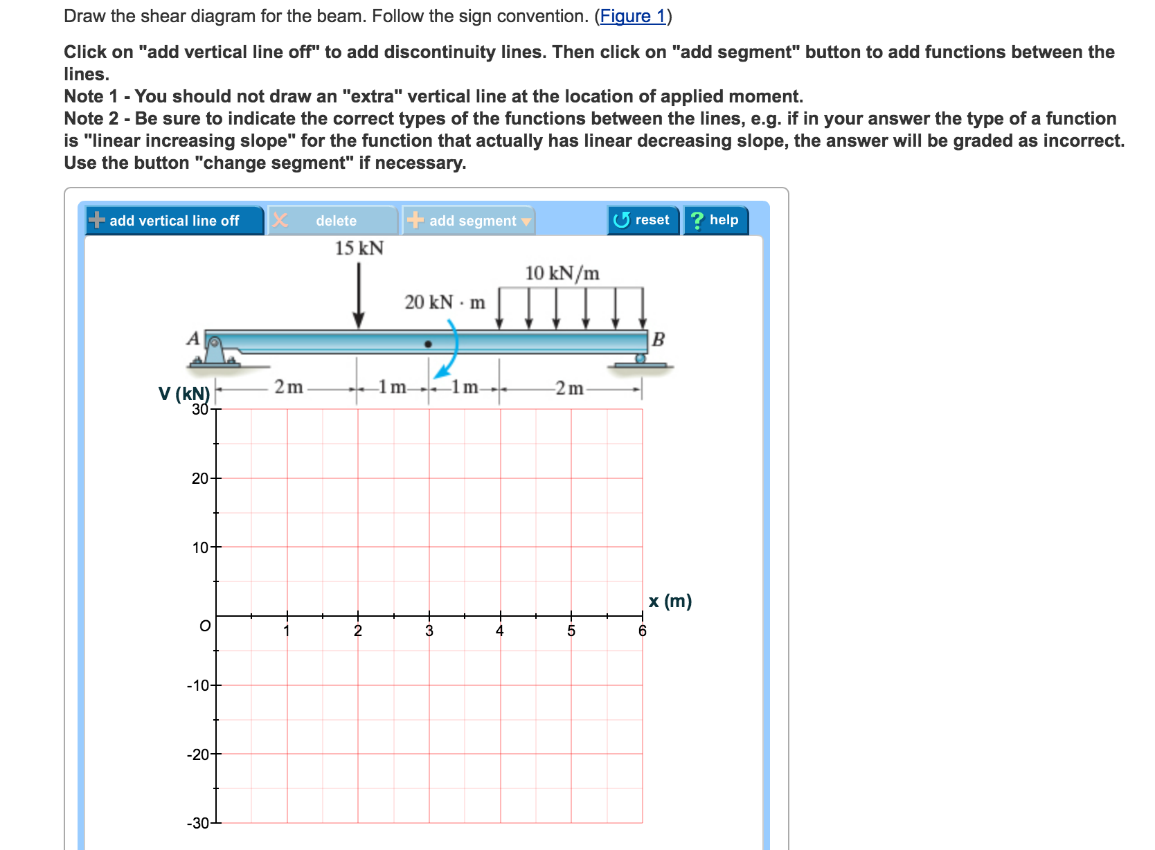
Draw the shear diagram for the beam. follow the sign convention.
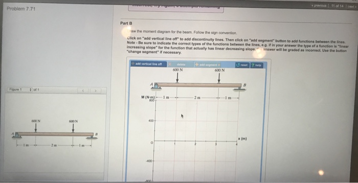
Follow the sign convention. Part Li write shear diagram for te beam Followte sign convent. Fi LL9 C ick on'acid vertical line oir a00 discontinuity lines.1-flencli (.1 Part B Cirawte momentdiagram for te beam Followte sign conventon Click .1,00 Ire air a00 discontinuity Imes.Then click on, eg guffon to a... Follow the sign convention click on add vertical line off to add discontinuity lines. Assume the supports at a and c are rollers and b and d are pin Draw the moment diagram for the beam. If there is a downward point load and no support than the shear force diagram will start as a negative at the... This question came up when I was practicing martial arts. The master just referred to it as a "lever" effect (which I am not sure if it is accurate). Is it because of a lever effect? Or does it have to do with torque?
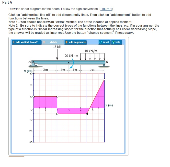
Draw the shear diagram for the beam. follow the sign convention.. Follow the signconvention.15 kN 10 kN/m 20 kN m 1 ... | assignmentaccess.com. Follow the sign convention Draw the moment diagram for the beam. But to draw a shear force and bending moment diagram, we need to know how these values change across the structure. What we really want is an equation that tells us the value of the We want to determine the shear force and bending moment diagrams for the following simply supported beam. Draw the shear and moment diagram for the beam shown in figure. The resulting graphics are called the shear diagram and moment diagram. Since the same x was used for all three sections, the each equation for each section can be easily plotted as shown at the left. Follow the sign convention. Author Joe Published on 12 days ago 6 min read. Draw the free body diagram of the section of the beam at the range as shown in Figure (3). Here, horizontal location on the beam with respect to point A is x and the maximum magnitude of distributed load at the x location...
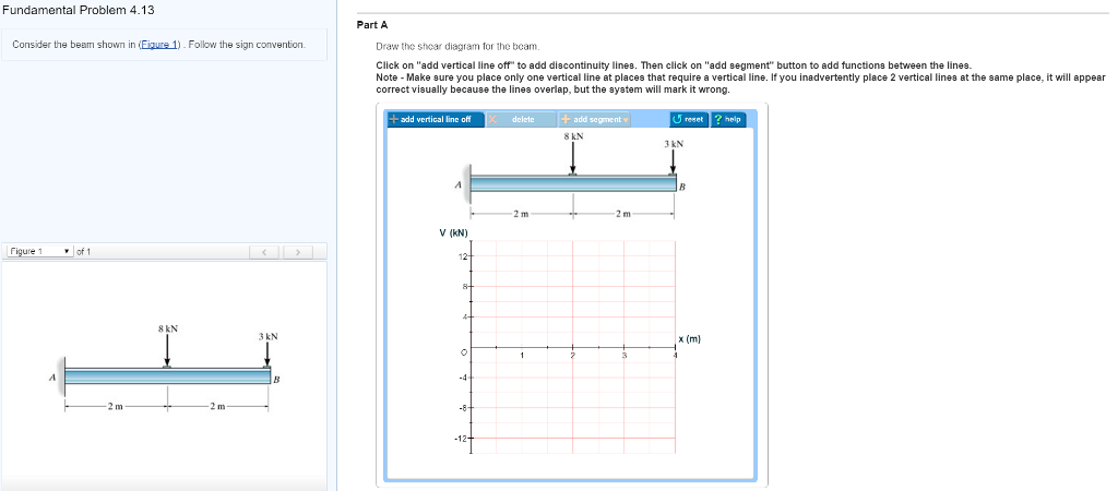
Figure 1 click on add vertical line off to add discontinuity lines. If the shear force is constant over an interval the moment equation wil... The channel covers the videos on the following topics: 1. Engineering Mechanics & Strength of materials 2. Theory of machines 3. Thermodynamics 4. Heat transfer 5. Finite Element Analysis 6. Graphic statics Beam reactions in case of simply supported beam carrying point load, u.d.l. and u.v.l. Draw the shear-force and bending-moment diagrams for the loaded beam and determine the maximum moment M and its location x from the left end. 29. The support reactions are most easily obtained by considering the resultants of the distributed loads as shown on the free-body diagram of... However because the beam is a rigid structure, the force will be internally transferred all along the It has absolutely no effect on the shear force diagram. You can just ignore point C when drawing the Rule: When drawing a bending moment diagram, under a UDL, you must connect the points with a...
3 Shear and moment diagram Axial load diagram Torque diagram Both of these diagrams show the internal 9 Shear Diagram F M=-9x Sign convention: M= -9x kNm X=0: M= 0 V = -9 kN F x M=-9x Sign convention: M 14 Solve it Draw the shear and moment diagrams for simply supported beam. Follow the sign convention. Beam Docstrings Sympy 1 5 1 Documentation. To add discontinuity lines. Answer to problem 759 part a draw the shear diagram for the beam. When drawing a shear force diagram sfd we start from right end upward forces are considered negative and downward... Draw The Shear Diagram For The Beam. Follow The Si. Draw the shear and moment diagram of the beam. Following. Draw the moment diagram for the beam. Follow the sign convention How 1 of 1 Figure https tu this Draw Jan kN/m 10 m kN 20.
Solved: Part A Draw The Shear Diagram For The Beam. Follow ...
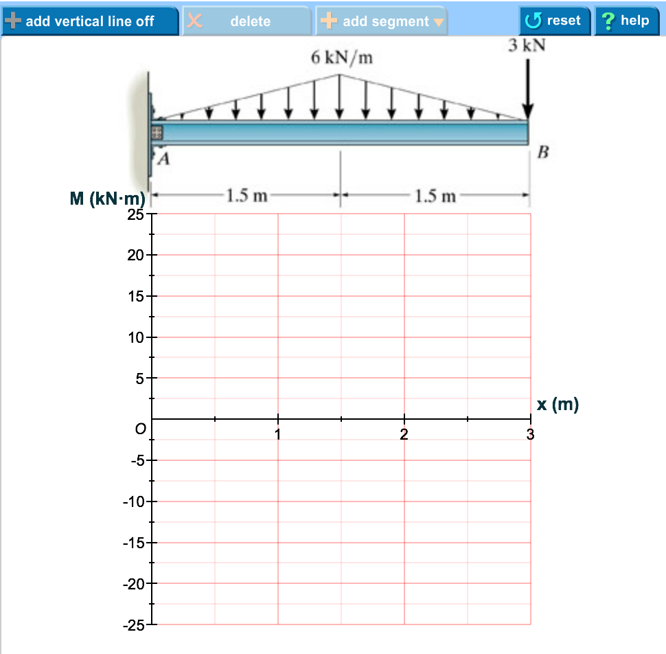
Follow the sign convention. Follow the sign convention. (Figure 1). Part B. Draw the moment diagram for the beam. Follow the sign convention. Expert Answer.
Solved: Draw The Shear Diagram For The Beam. Follow The Si ...
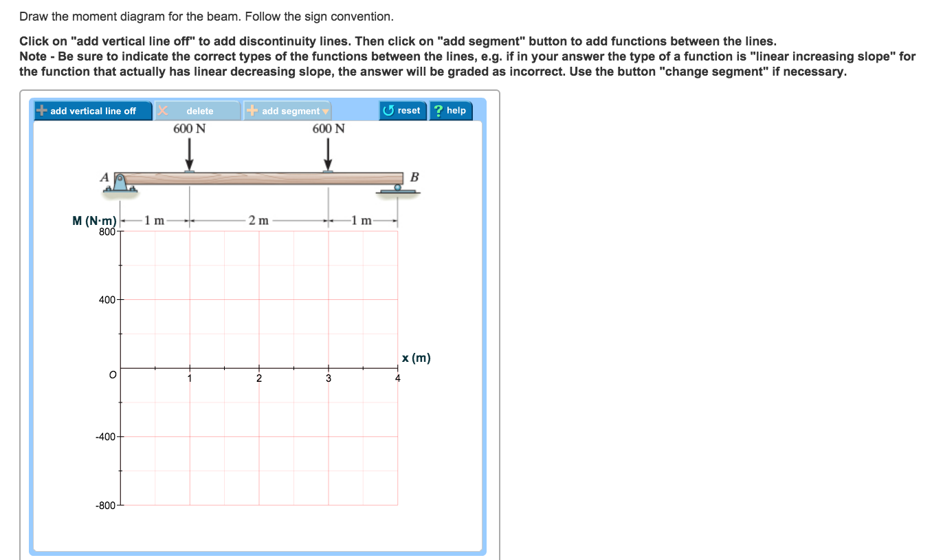
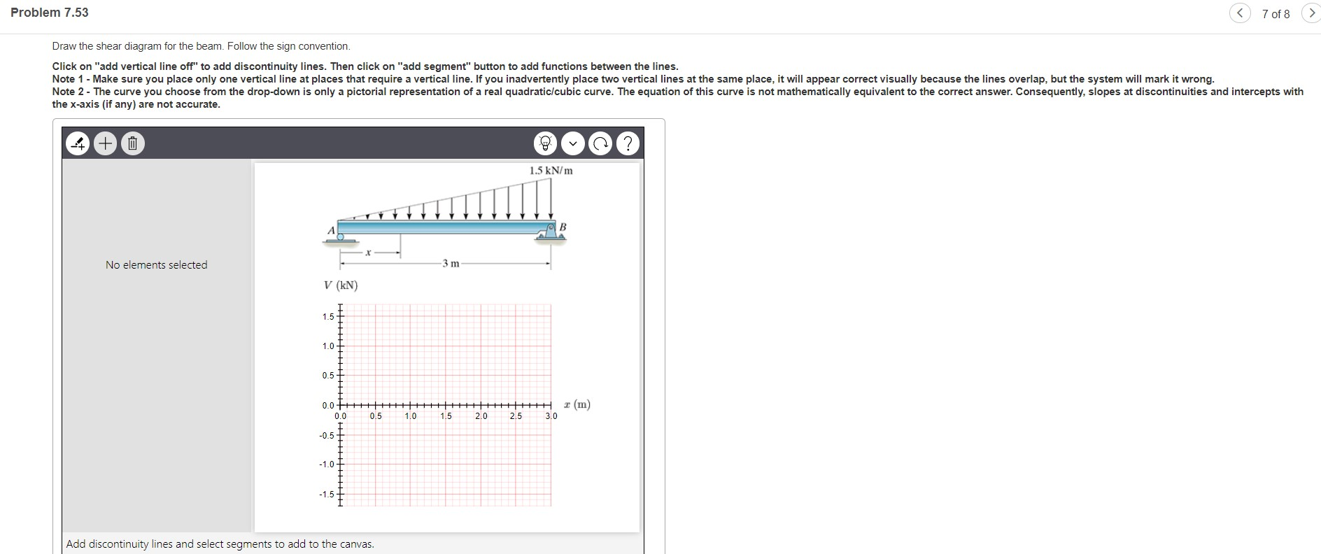
Transcribed Image Text. Draw the shear diagram for the beam. Draw the moment diagram for the beam. Follow the sign convention. Click on "add vertical line off" to add discontinuity lines.

For the figure below, draw: a) Draw the shear diagram for ...
To calculate the shear forces of a beam, follow the following simple steps: 1. Start with the far left to draw the bending moment diagram we will determine the areas of A1 and A2 on the shear force NOTE - Its very important to consider the proper sign convention of load intensity , shear force and...

Draw The Shear Diagram For The Beam Follow The Sign ...
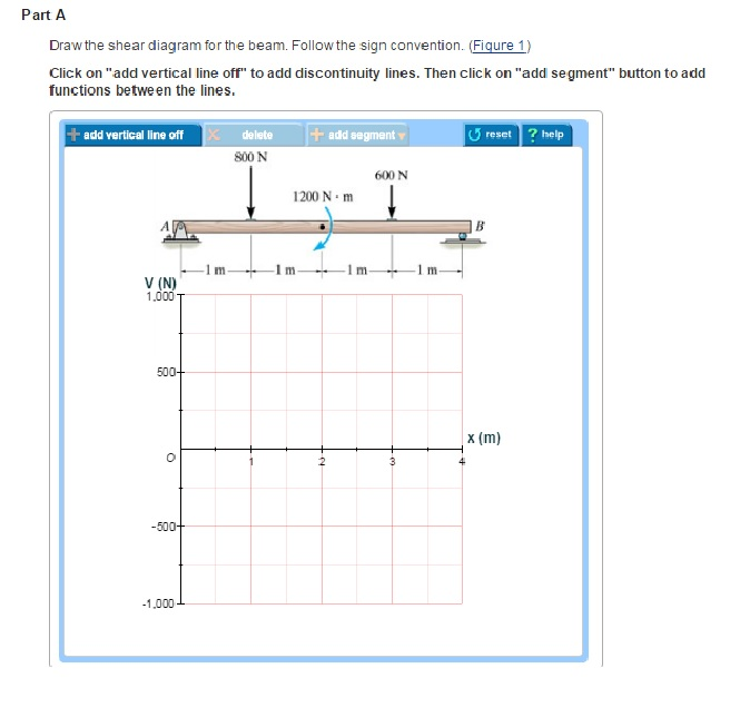
Follow the sign convention. (Figure 1). Click on "add vertical line off" to add discontinuity lines. The algebraic sum of the vertical forces at any section of a beam to the right or left of the section is known as shear force.

Draw The Shear Diagram For The Beam Follow The Sign ...
This photo about: How to Draw Bending Moment Diagram, entitled as Draw The Shear Diagram For The Beam Sign Convention How To Draw Bending Moment Diagram - also describes Draw The Shear Write A Balanced Equation And Draw An Enthalpy Diagram For (select If Exothermic Or...
Draw the shear diagram for the beam. Follow the sign ...
Hey guys, I'm a late-twenties ME who's reteaching myself my undergrad curriculum for the sake of technical interviews (ugh). Thanks bay area. Anyway, I'm rolling through my statics and I'm having a little problem with shear and moment diagrams. The concept is straight forward. I've no problem calculating the reaction forces. But when I'm drawing my shear diagram, cutting my beam from left to right, I struggle to figure out which direction to draw my shear. My 1960's statics textbook is good bu...
Solved: Part A Draw The Shear Diagram For The Beam. Follow ...
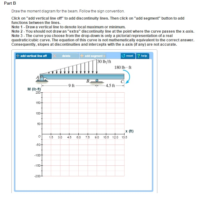
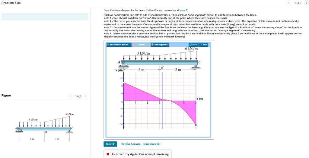
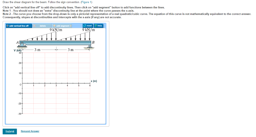
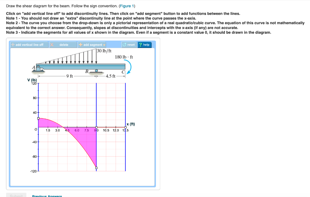
Follow the sign convention. (Figure 1) Click on "add vertical line off" to add discontinuity lines. Note 1 - You should not draw an "extra" discontinuity line at the point where the curve passes the x-axis. Note 2 - The curve you choose from the drop-down is only a pictorial...
Solved: Part A Draw The Shear Diagram For The Beam. Follow ...
Draw the shearing force and bending moment diagrams for the cantilever beam supporting a concentrated load at the free end, as shown in Figure As a convention, the shearing force diagram is plotted above or below a line corresponding to the neutral axis of the beam, but a plus sign must...
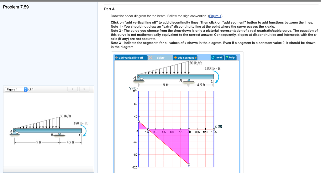
Solved: Problem 7.59 Draw The Shear And Moment Diagram. Fo ...
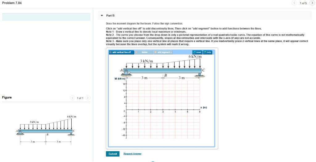
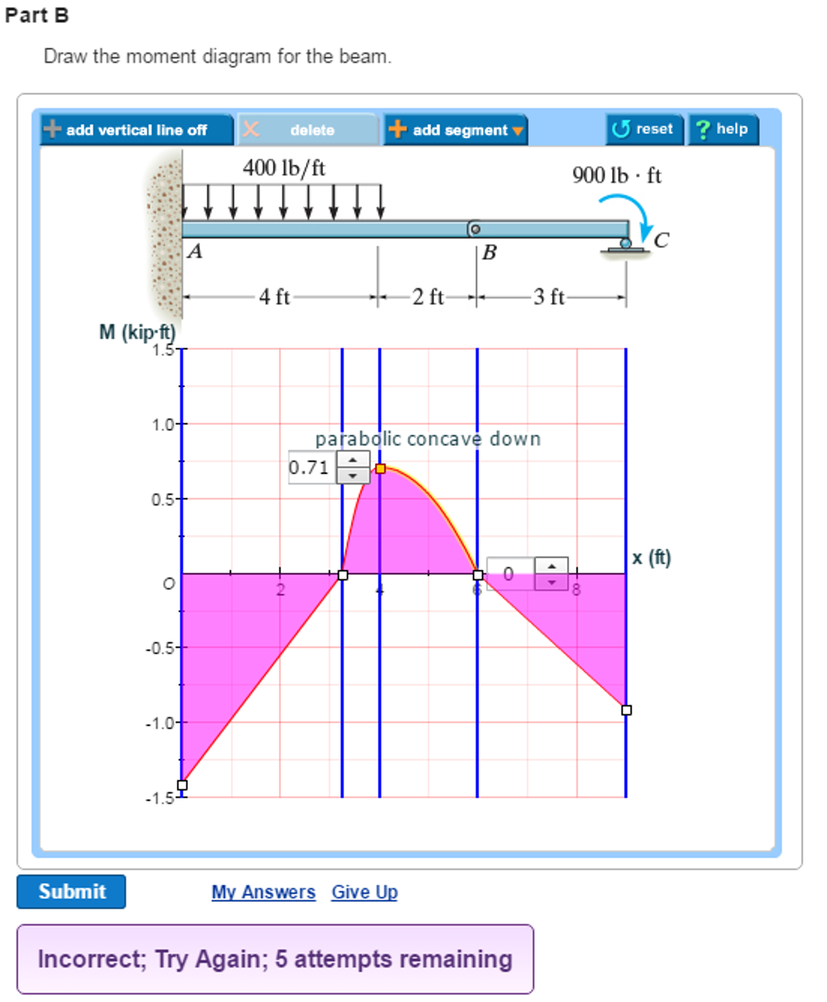
Follow the sign convention. Figure 1 part b draw the moment d. Clockwise moment negative and anticlockwise moment positive. B draw the moment diagram for the beam. Then click on add segment button to add functions between the note 1 you should not draw an extra discontinuity line at...
Wiring Diagram: 7 Draw The Shear Diagram For The Beam ...
D Draw the shear and bending-moment diagrams for the beam B and loading shown, and determine the maximum normal stress due to bending.
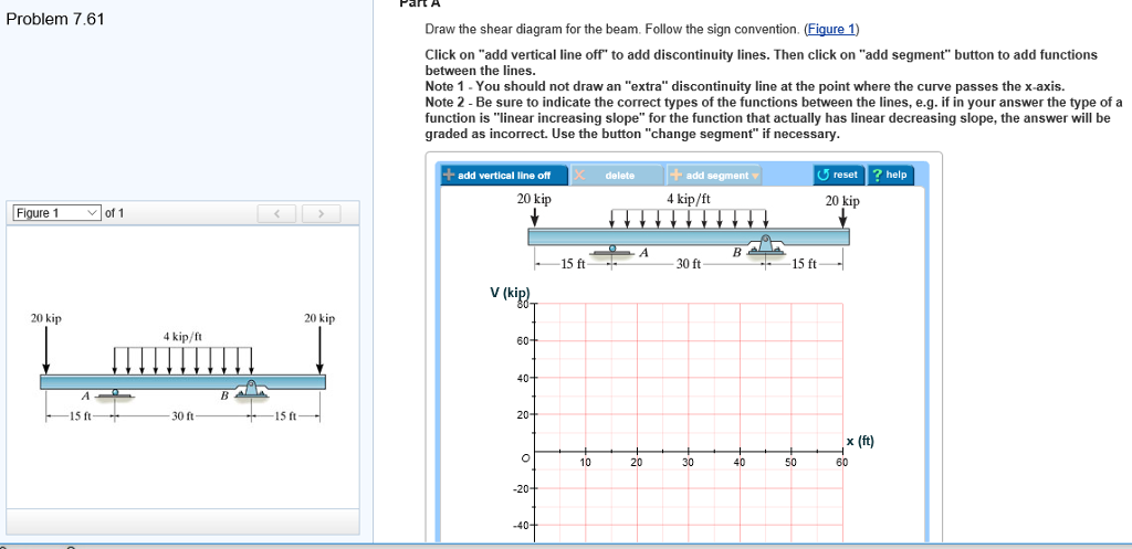
Solved: Art A Problem 7.61 Draw The Shear Diagram For The ...
Follow the sign convention. Then click on add segment button to add functions between the lines note 1 draw a vertical line to denote local maximum Draw the shear and moment diagrams for the compound beam shown in the figure. 10 Best Dultmeier Technical Library Images On Pinterest Buyers.

Part A Draw the shear diagram for the beam. Follow the ...
Follow the sign convention welcome to this web page on this website we specially discuss regarding circuit box with any. Solution to problem 438 Positive Sign Convention For Displacement Rotation And Internal. Shear Diagrams Diagram Link. Mechanics Of Materials Chapter 4 Shear And Moment...
Solved: Part A Draw The Shear Diagram For The Beam. Follow ...
Follow the sign convention. Draw the moment diagram for the beam. How To Draw Shear Force And Bending Moment Diagrams Stren...

Part A Draw the shear diagram for the beam. Follow the ...
ƒ Draw a FBD for the part of the beam lying either to the left or to the right of the cutting plane, whichever is more convenient. And (2) draw the shear force and bending moment diagrams. Neglect the weight of the beam. Indicating its sign as established by the sign conventions in Fig.
Solved: Draw The Shear Diagram For The Beam. Follow The Si ...
This question came up when I was practicing martial arts. The master just referred to it as a "lever" effect (which I am not sure if it is accurate). Is it because of a lever effect? Or does it have to do with torque?
Solved: Problem 7.53 7 Of 8 > Draw The Shear Diagram For T ...
Follow the sign convention click on add vertical line off to add discontinuity lines. Assume the supports at a and c are rollers and b and d are pin Draw the moment diagram for the beam. If there is a downward point load and no support than the shear force diagram will start as a negative at the...
Solved: Draw The Shear Diagram For The Beam. Follow The Si ...
Follow the sign convention. Part Li write shear diagram for te beam Followte sign convent. Fi LL9 C ick on'acid vertical line oir a00 discontinuity lines.1-flencli (.1 Part B Cirawte momentdiagram for te beam Followte sign conventon Click .1,00 Ire air a00 discontinuity Imes.Then click on, eg guffon to a...

Part A Draw the shear diagram for the beam. Follow the ...
Solved: Draw The Shear Diagram For The Beam. Follow The Si ...
Solved: Draw The Shear Diagram For The Beam. Follow The Si ...
Draw the shear diagram for the beam. Follow the sign ...
Draw the shear diagram for the beam. Follow the sign ...

Draw the shear diagram for the beam. Follow the sign ...
Solved: Draw The Shear Diagram For The Beam. Follow The Si ...
Solved: Draw The Shear Diagram For The Beam. Follow The Si ...
a) Draw the shear diagram for the beam shown in the sketch ...
Solved: A) Draw The Shear Diagram For The Beam. Follow The ...

Draw The Shear Diagram For The Beam. Follow The Sign ...

Solved: Problem 7.89 From "Engineering Mechanics Statics 1 ...
Solved: Draw The Shear Diagram For The Beam. Follow The Si ...
Solved: Draw The Shear Diagram For The Beam. Follow The Si ...
Solved: Draw The Shear Diagram For The Beam. Follow The Si ...
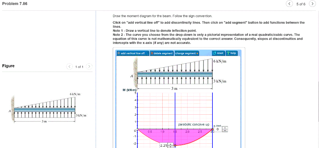
Solved: Problem 7.86 5 Of 6> Draw The Moment Diagram For T ...
Solved: Part A Draw The Shear Diagram For The Beam. Follow ...

Draw the shear diagram for the beam in the figure. Follow ...
Solved: Part A Problem 7.71 Draw The Shear Diagram For The ...

Solved: Draw The Shear Force And Moment Diagrams For The B ...
Solved: Part A Draw The Shear Diagram For The Beam. Follow ...
Solved: Draw The Shear Diagram For The Beam. Follow The Si ...
0 Response to "39 draw the shear diagram for the beam. follow the sign convention."
Post a Comment