40 grease trap piping diagram
Grease Trap/Grease Interceptor A grease trap/grease interceptor is the device utilized to effect the separation of grease and oils in wastewater effluents from food service establishments. Such traps or interceptors may be of the "outdoor" or below ground type normally referred to as large grease interceptors, or the "under-the-counter" package ... A grease trap is designed to prevent greasy substances from entering plumbing systems, septic tanks, and waste water treatment facilities where they are difficult to process and may create a number of environmental problems.
Odor from accumulated grease in an interceptor may pass back through the piping system and through the drain opening.An additional trap should be considered between the fixture and interceptor. Consult local codes. Zurn interceptors are manufactured standard with a removable cleanout

Grease trap piping diagram
May 09, 2019 · You’ll want to replace the P-trap (and all other pipe with grease in it). You should be able to remove the P-trap and see the grease if it’s in the rest of the line. You can always clean out the p-trap but it’s a messy smelly job and can’t be done at any sink or toilet. It’s well worth $15 to not have to deal with the mess. • The plumbing code does not prohibit discharge of a food waste disposer downstream of the interceptor. • Mixed reviews on this: - Studies have indicated that dishwasher prerinse sinks are a significant source of grease and food waste grinders are often installed with the prerinse sink - Since a food waste grinder operates best with a cold 46 25 23 - Grease Traps. 46 25 00 - Oil and Grease Separation and Removal Equipment. 46 25 13 - Coalescing Oil-Water Separators. Remove Filter. Default Recent. 43 CAD Drawings for Category: 46 25 23 - Grease Traps.
Grease trap piping diagram. The International Plumbing Code (IPC) 1002.1 (exception 3) allows a grease interceptor to serve as a fixture trap - where it is intended by the manufacturer to serve as a trap - for a single fixture or a combination sink of not more than three compartments so long as the vertical distance from the outlet of the fixture to the inlet of the interceptor is not more than 30 inches and the ... guidance found in both the 2009 International Plumbing Code (IPC) Commentary and the Uniform Plumbing Code (UPC), Appendix H. Size, type, and location of grease traps shall be in accordance with the manufacturers' instructions, the requirements of City of Fort Worth Environmental Ordinance #12274 and Plumbing Ordinance #15951. Manual grease trap designs date back to the Victorian days. Nathaniel Whiting was the first person to obtain a patent for a grease trap. Grease traps are usually constructed from stainless steel or plastic and must be cleaned occasionally. How To Install A Residential Grease Trap Part I: Guidance for Grease Trap Sizing and Design Criteria A. Introduction The City of Carrollton requires grease traps or interceptors in commercial food establishments to prevent the entry of grease, fats, oils and debris into the city's sanitary sewer system. These substances cause sewer back-ups, blockages, and sanitary sewer overflows.
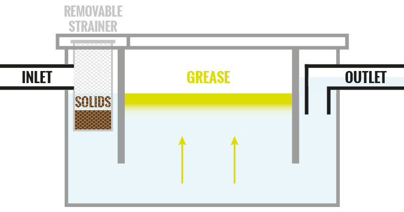
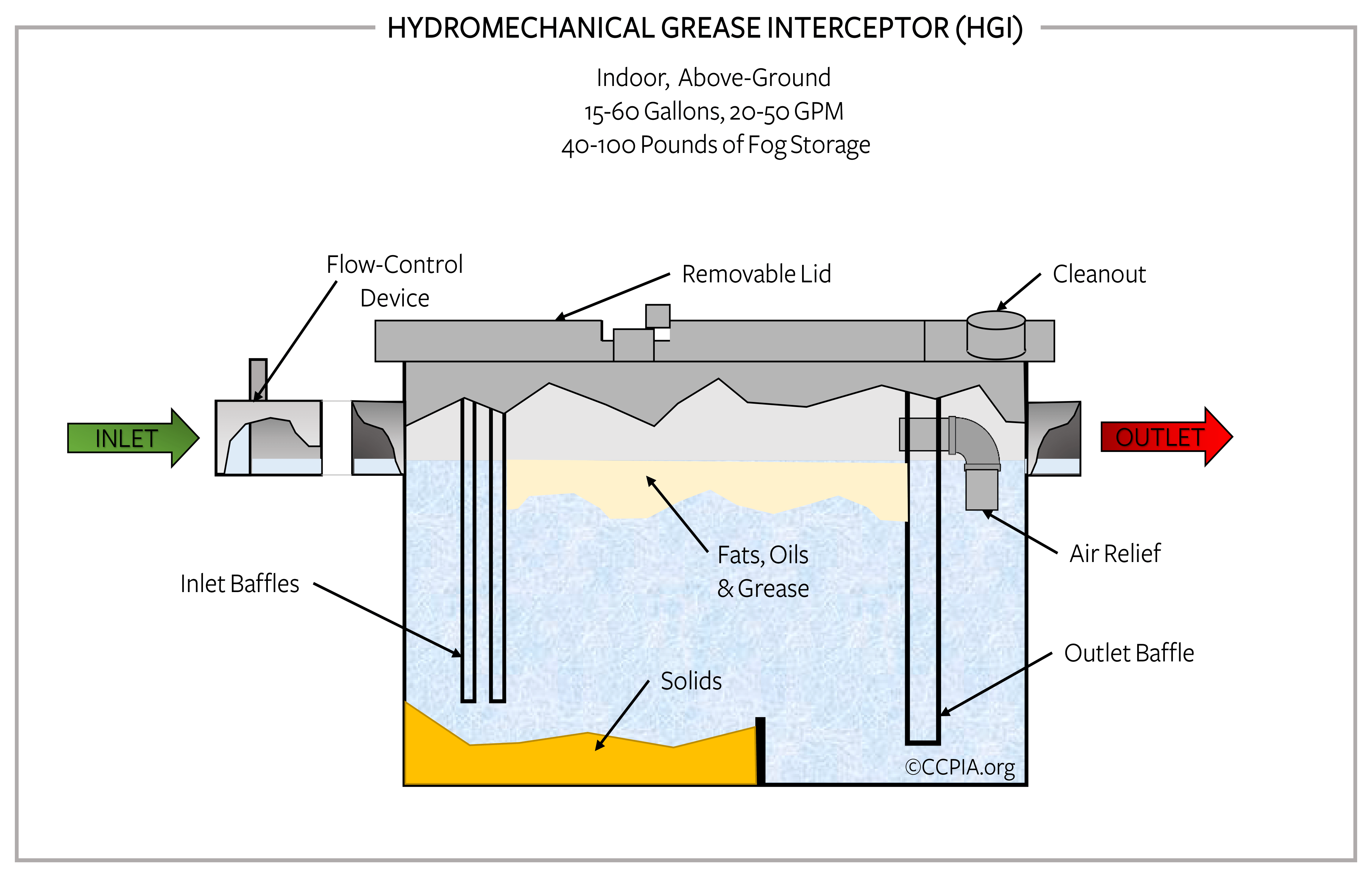
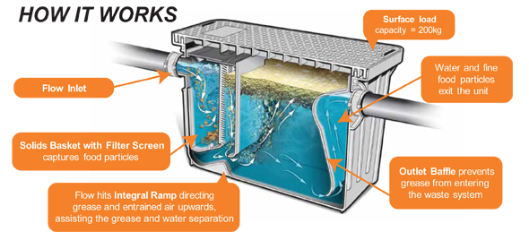
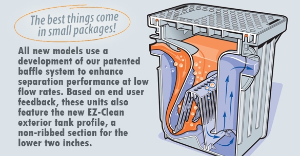
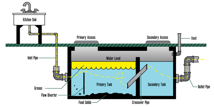
Without grease interceptors, fats, oils and grease will build up on the walls of drainage piping, ultimately causing a blockage. This can lead to an immediate back-up in your kitchen, or worse, the city's wastewater collection system. the grease and water layers downward toward the bottom of the interceptor (Diagram E). If pressure continues to build, grease would eventually be forced under the baffle plate and out of the unit. The presence of a vented flow control device and air relief by-pass is a key element in the efficient operation of a grease interceptor. If one XL Grease Trap 75 GPM - CAD Drawing 1. XL Grease Trap 75 GPM - CAD Drawing 2 - In Ground Installation. XL Grease Trap 75 GPM - CAD Drawing 3. XL Grease Trap 75 GPM - CAD Drawing 4 - Not Traffic Rated. XL Grease Trap 75 GPM - CAD Drawing 5 - In- Ground Installation M-Rated Cover. How a Grease Interceptor Works (see diagram following table). A Flow from undersink grease traps or directly from plumbing fixtures enters the grease interceptor. The UPC requires that all flow entering the interceptor must enter through the inlet pipe B
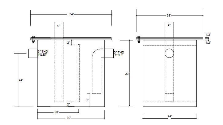
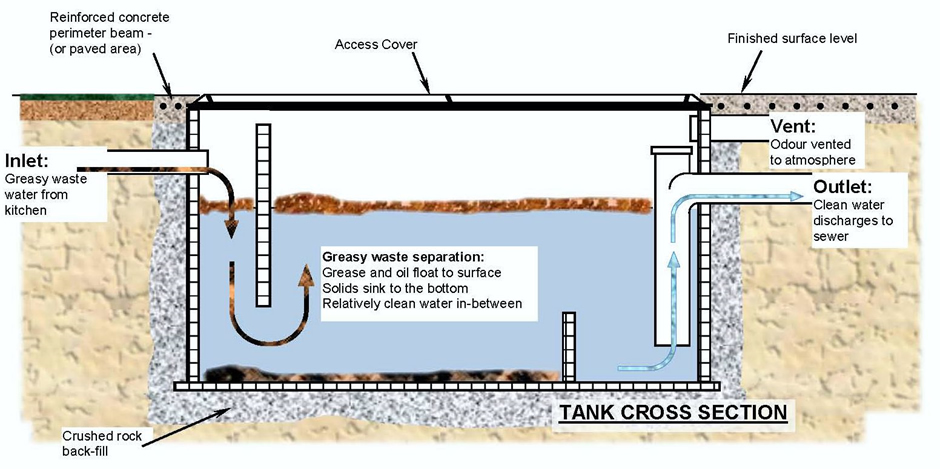
This diagram illustrates some of the processes and movement of water in a more natural or non-urbanised environment where most of the soil is permeable to water. Urban areas have large areas of hard surfaces, impermeable to water such as roofs, roads, paved and concrete areas. Grease traps usually consist of an underground, watertight, concrete tank with baffled inlet and outlet piping. The outlet pipe has a tee that allows the internal discharge to be located within 0.3 m of the tank bottom. The size of the grease trap depends on the anticipated flow rate, water temperature, and grease concentration. Creating a grease trap diagram can help you keep track of the trap's interior. Without a grease trap diagram for reference, it will be more difficult to properly re-install all the parts after cleaning. Measure the grease. Place a measuring stick in the trap and keep moving it down slowly until it reaches the bottom. • All piping inside the grease interceptor must be PVC Schedule 40. • Procedures or physical measures must be in place to make evidence of tampering or unauthorized use immediately apparent to the GI owner/representative. ... ReWaFOG-2015_Grease Interceptor Diagram
Ordinance concerning Food Service Establishments and Fats ...
The problem is, even though it wasn’t intended to catch items that fall in the sink, that’s exactly what it can do. All of our soaps, shampoos, conditioner, and other lotions and creams have the same effect as oil and grease in the kitchen. They coat the piping, including the P-trap area, and are a good place for clogs to form.

19 Inspirational Inside Grease Trap
We stand behind the quality of our products and will make things right if you are not satisfied. All products sold from Drain-Net have a 1 year limited warranty from date of purchase against defects in material or workmanship, under normal use.

Grease Trap Cleaning | Maryland's Premier Liquid Waste Company
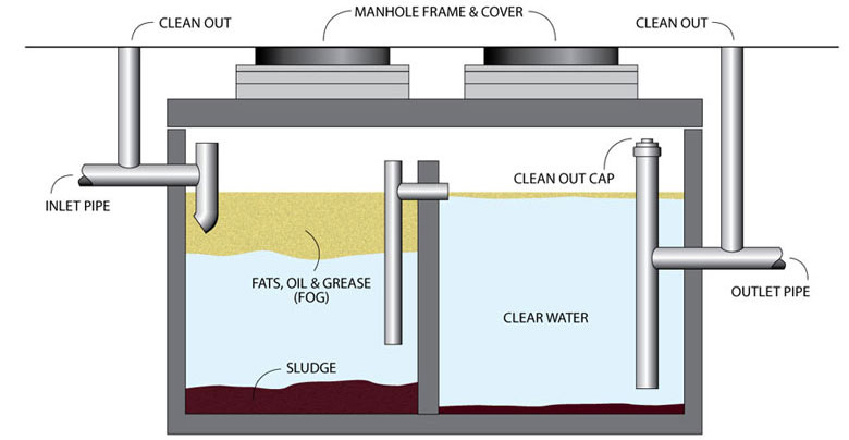
Grease interceptors will separate all lighter-than-water substances, collecting them inside the interceptor, above the static water line. Design criteria is determined by plumbing code, typically following guidelines set forth by The Plumbing & Drainage Institute (PDI), which tests and rates interceptors. The accepted
.jpg)
Grease Trap Piping Diagram / Grease Trap Fat Trap ...
Grease traps and the contributing plumbing configuration must be approved by the City of Bloomington Utilities Department prior to installation. For more information, please contact the CBU Pretreatment Program Inspector at 812-349-3934.
Grease Trap Piping Diagram - Free Wiring Diagram
piping in the grease trap should be sufficient to allow gravity-differential separation to the grease so that it will not escape hrough t e ou tle. The minimu horizontal distance shall be twenty-four inches. M104.12 Access/Covers 04.12.1 Access from the top of the grease trap shall be
What is a Grease Trap & How Does a Grease Trap Work ...
4. Grease traps must be installed in the plumbing system for restaurants and businesses that prepare food. The location and size of the grease interceptors must be included on the isometric drawing. For further information see the Building Inspections handout titled Grease Interceptors in Kitchens. 5.

Closeup of skeleton hand model
and similar equipment and to prevent grease accumulations from clogging connecting piping and sewer lines. In 1883, one Nathaniel T. Whiting of California applied for a patent on a grease trap, which was issued in October of 1884. Whiting's design principle was not unlike that of present day grease interceptors.
Difference Between Grease Traps and Grease Interceptors ...
Grease Separators G Series G-C Series GF Series RTO Series GIS Series Grease Separator Sizing Installation Diagrams Grease Separator Cleaning Rep Search Contact Us Protect waste lines against blocking and stoppages. Select a separator with a gallon-per-minute flow equal to the initial tank discharge capacity. Draw-off valve available. With an internal flow control, an external […]

Grease Trap Installation Diagram - Diagram Resource Gallery
Piping Connections All Endura Grease Interceptors are manufactured with no hub connections. Standard mechanical joint couplings can be used to connect the grease interceptor to a metal or plastic piping system. If the piping system needs tobe resized, use appropriate mechanical joint reducers, but do notdecrease pipe diameter across the unit.
32 Grease Trap Piping Diagram - Wiring Diagram Database
Piping Handbook (7th Edition) Sandi Subakti. Download PDF. Download Full PDF Package. This paper. A short summary of this paper. 9 Full PDFs related to this paper ...
Grease Trap Piping Diagram / Grease Trap Fat Trap ...
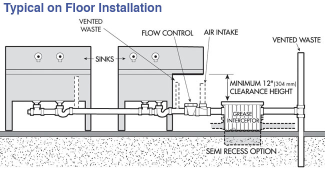
Internal (Under the Sink) Grease Trap Diagram Vent Pipe Must be lower than sink drain Flow Restrictor Grease Trap . FLC SERIES AppROVED SINKS OPTIONAL p _ TRAP VENT (AIR INTAKE) CLEANOUT FLOW ORIFICE PLATE INLET VENT OUTLET VENT FLOW CONTROL ZURN LICHT COMMERCIAL SERIES 2700 INTERCEPTOR . Title: Microsoft Word - Document1 Author: mar06302 ...

What Is a Grease Trap and How Does It Work?
The definition of a grease trap is " a trap in a drain or waste pipe to prevent grease from passing into a sanitary sewer lines and system." A grease trap/grease inceptor is in simple terms a plumbing fixture that contains decomposing food waste, bettering the sewer system. There are three main types of grease traps:

Plumbing a grease trap | Pro Construction Forum | Be the Pro
Each compartment, 18 inches by 18 inches by 8 inches with 1.5-inch sink drain and trap. Vegetable prep sink, 18 inches by 18 inches by 6 inches, 1.5-inch trap and 1.5-GPM faucet. Wash sink with one set of faucets. Mop basin, 24 inches by 24 inches by 6 inches, 2-inch trap, faucet at 5-GPM max. Other.

Commercial Grease Trap Pitfalls That Can Hurt Your Business
Grease Traps-The First Line of Defense. Grease traps also known as grease interceptors are plumbing systems that serve as our first line of defense when it comes to preventing fats, oil and grease (FOG) from entering the water waste management system and eventually the ocean. A grease trap, which is usually made of hard plastic, fiberglass or concrete and placed inside the kitchen or buried ...

GREASE TRAP PUMPING
Grease Interceptor Sizing and Installation Guidelines E-102 Grease protection is an essential element for restaurants, cafes, catering facilities, commissaries, hotels, cafeterias, convenience stores, full service grocery stores, schools, hospitals, and food manufacturing plants.

Emergency Pumping and Plumbing: Got Grease Traps ...
Approved unions shall be permitted to be used in drainage piping where accessibly located in the trap seal or between a fixture and its trap; in the vent system, except underground or in wet vents; at any point in the water supply system; and in gas piping as permitted by Section 1212.5.
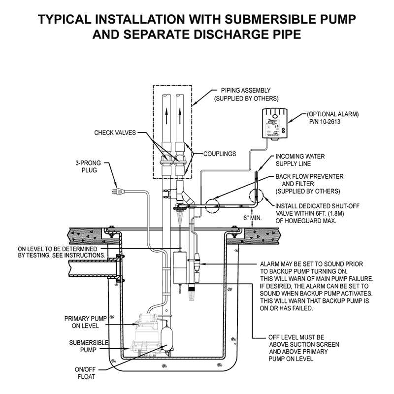
How to Install a Water Powered Emergency Backup Sump Pump
grease waste piping center line piping legend miscellaneous p = san, vent stack or domestic water riser st = storm drain leader riser f = fire standpipe riser equipment designation detail designation sheet note number revision number plumbing legend and abbreviations riser no. riser equipment equipment no. dwg. sheet no. detail number p 1 cp 1 ...

Grease Trap Piping Diagram - Drivenhelios
46 25 23 - Grease Traps. 46 25 00 - Oil and Grease Separation and Removal Equipment. 46 25 13 - Coalescing Oil-Water Separators. Remove Filter. Default Recent. 43 CAD Drawings for Category: 46 25 23 - Grease Traps.

How A Septic System Works Lovely Grease Trap Pumping ...
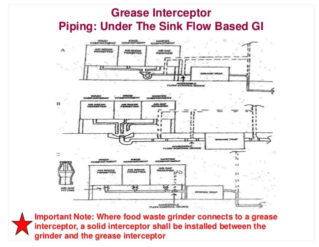
• The plumbing code does not prohibit discharge of a food waste disposer downstream of the interceptor. • Mixed reviews on this: - Studies have indicated that dishwasher prerinse sinks are a significant source of grease and food waste grinders are often installed with the prerinse sink - Since a food waste grinder operates best with a cold

Juli 2017
May 09, 2019 · You’ll want to replace the P-trap (and all other pipe with grease in it). You should be able to remove the P-trap and see the grease if it’s in the rest of the line. You can always clean out the p-trap but it’s a messy smelly job and can’t be done at any sink or toilet. It’s well worth $15 to not have to deal with the mess.
Mep restaurant and dining

Low Boy Grease Interceptor 50 LBS / 25 GPM - Drain-Net ...
How Grease Trap Cleaning Works | Sweet Honey

Ipex 3915A02C - Grease Trap Interceptor - 30 Lb Capacity ...

Grease and Oil in Restaurant Wastewater : Barnstable ...

The Interceptor Whisperer: Trapping and Venting for Grease ...
Compact Plastic Grease Trap 15 GPM | Endura
Grease Trap Piping Diagram - Free Wiring Diagram
Grease Trap Cleaning Services Melbourne | Emptying Triple ...

Wiring Diagram: 35 Grease Trap Piping Diagram

Grease Trap Piping Diagram - Free Wiring Diagram

Septic Medic Pumping and Plumbing: What is a Commercial ...
JFC - Grease Traps

Grease Trap Piping Diagram - General Wiring Diagram
Why do councils make restaurants install Grease Traps ...

Grease Trap Piping Diagram / Grease Trap Fat Trap ...

Grease Trap Cleaning Service | Gulliford Septic & Sewer

Steam Canada London | Grease Trap Cleaning, London Ontario

Grease interceptor - Page 6 - Plumbing Zone - Professional ...

EnviroZyme® Provides Controlled Grease Treatment for Traps
0 Response to "40 grease trap piping diagram"
Post a Comment