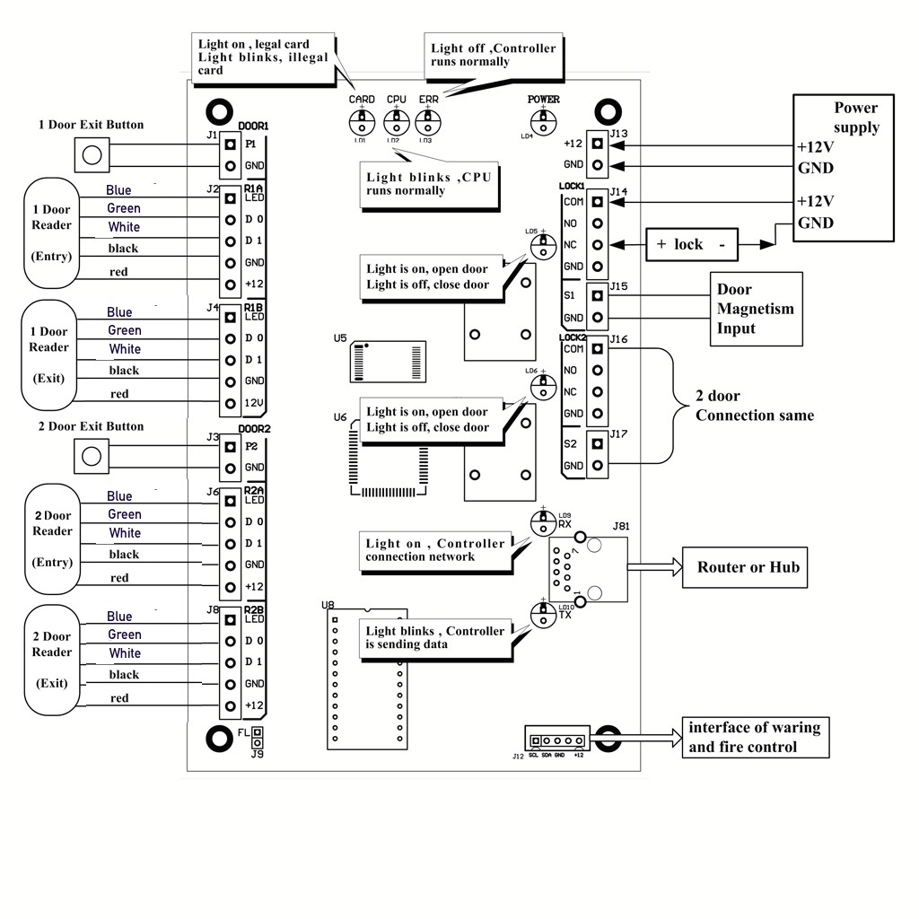
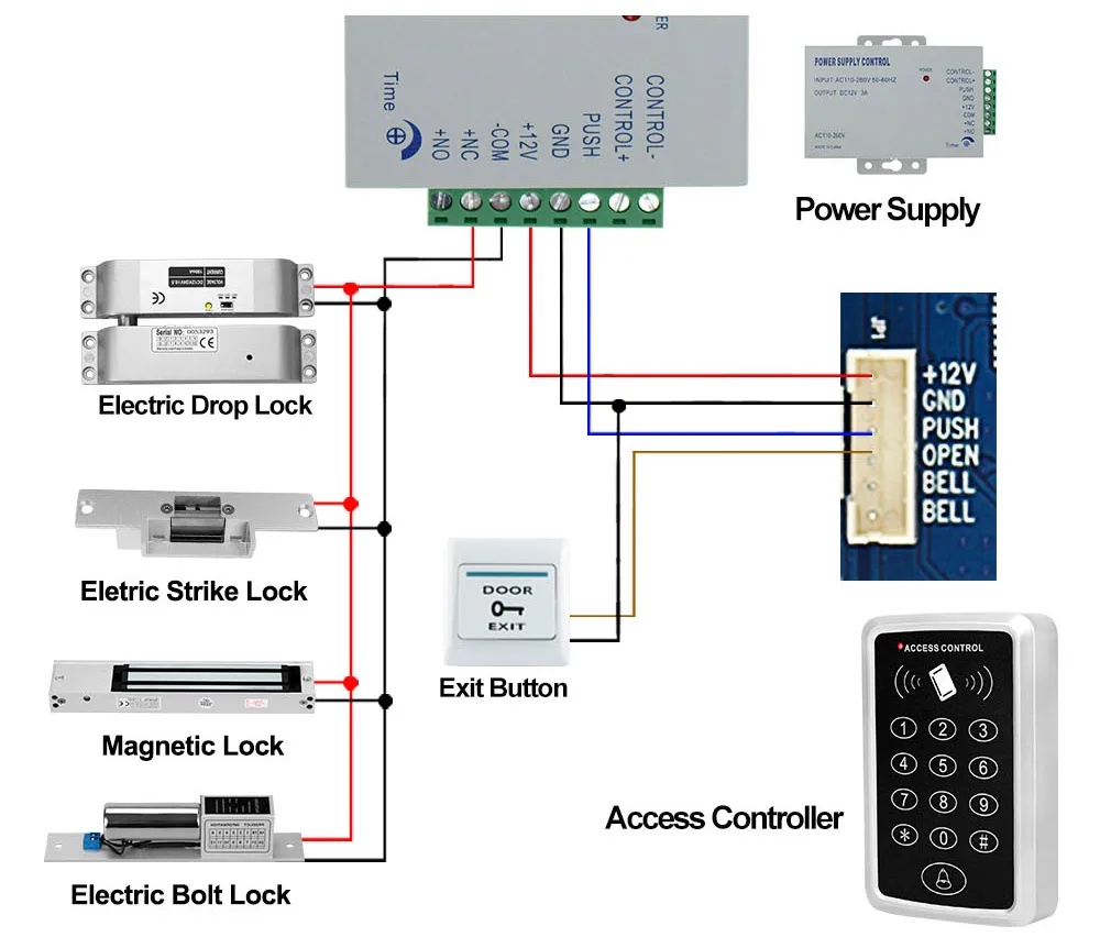
35 access control card reader wiring diagram
The following common wiring diagrams are available: One Single Door with Panic Bar Electric Latch Retraction, with Auto Operator Delayed egress - Fire Rated Application Auto Operator and actuator Electric Latch Retraction Electric Latch Retraction with Remote Push Button - Fire Rated Application Fail Secure electric strike and card reade r SELF-CONTAINED ACCESS CONTROL SYSTEMS 232i Indoor Keypad 232w Weather-Resistant Keypad 232se Sealed Environment Keypad 232r Ruggedized Keypad 232iLM Mullion Keypad 233 Card Reader System 234 Card Reader/Keypad System FEATURES • Lock Release Relay • Lock Release Time • Alarm Zone Shunting Relay • Multiple User
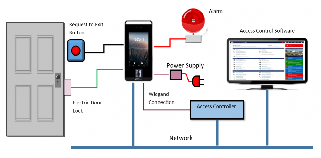
Access Control Systems An access control system is an integration of hardware, software, and management tools that electronically monitor and control access through door, gates, elevators, and many other entry points. Access control systems are found virtually everywhere. They can be found in Hotels, Hospitals, Airports, Banks,
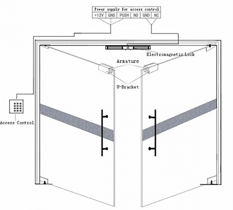
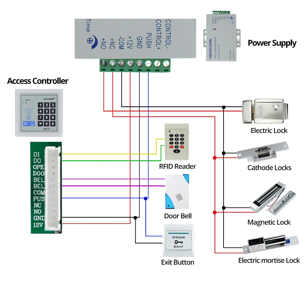
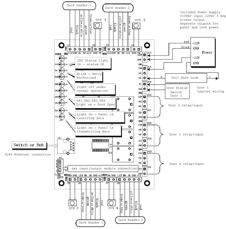
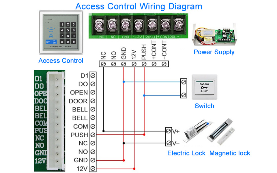
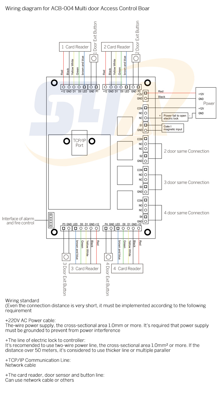
Access control card reader wiring diagram
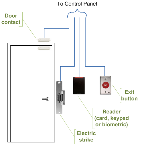
2.2.1 Card reader technologies 7 2.2.2 Credentials technology 7 ... Room Access control hardware RS-485 Readers Wiegand Readers Wiring topology bus, ("chain") star Maximum cable length 1200m 100m Number of wires needed for the reader ... 2.2.3 Wiring for non-reader components A wiring diagram is a straightforward visual representation of the physical connections and physical layout of your electrical system or circuit. It shows the way the electrical wires are interconnected and will also show where fixtures and components could be attached to the system. In an access control system, use Cat 5 to connect the ACU to the LAN (internet). To connect credential readers to the ACU, use 22 gauge 6 conductor shielded cables. Credential readers must be within a 500-foot distance from the ACU for the reader to work properly.
Access control card reader wiring diagram. Access Control Composite Cables | PB00093 | V3_ECOS_BDC_0617_A_AG Belden Lock Power Part Number Flame Rating (Gray) Card Reader (Orange) Door Contact (White) Request Exit/Spare (Blue or Yellow) Assembly Standard 558AFS CMR 4C, 18 AWG, Shielded 3 Pr, 22 AWG, OA Shield 2C, 22 AWG, Shielded 4C, 22 AWG, Shielded (Blue) 658AFS CMP Banana Peel ... Graphics Card : Compatible with DirectX 12 or later Disk Drive ... Supports the following issues, language, viewing ESM HTMLs, access and viewing electronic wiring diagrams. Download: ESM HTML and EWD Troubleshooting: top of page: 8 : Zooming in on PC Touch Screen Under ASIST : You can use pinch-to-zoom on ASIST lists and PDF files. Touch two fingers on the touch … The D21x series features a built-in 125 kHz RFID reader for access control (Active Reader Passive Tag (ARPT) system), as specified in ISO/IEC 18000-2:2009 Part 2 which makes them compatible with other third party key fobs and card entry systems. A maximum of up to 200 key fobs can be registered. D11x series: The following diagram shows the wire types and max lengths that are recommended for use with the Verkada AC41. We recommend using one twisted pair for - (ground) and + (power) and one twisted pair for the data (D0/D1, in the case of a Wiegand reader, or A/B, in the case of a Verkada Reader).
Cable Conduit (Punch Hole for cables) Temper Switch InBio Pro Panel Heat Dissipation Grill Power Supply Backup Battery State Indicators Mounting Holes Inserting Panel to Rail Mounting Rail We recommend drilling the mounting plate screws into solid wood (i.e. stud/beam). CARD READER DOOR: Allows entry using access card, scheduled locking and . CAAMS are manufactured by Lenel, a unit of United Technologies Corporation . Point-to-point wiring diagrams may be included within shop drawings instead . Lenel offers a Dual Reader Interface (DRI) module for business access control solutions. . Door Access Control System Electromagnetic Lock Wiring Diagram Installation Price CHOICE RFID Card + Password Reader DA188 $ 78.00 Quick Shop Add … The diagram at right illustrates an example of proper wiring on an SCP controller for both supervised and unsupervised inputs. Wiring for an SIO dual reader board follows similarly (Figure 2). Credential Structures Existing installations using an SCP controller require a thorough assessment of all card formats in use, and a
Access control card reader wiring diagram collection. Single door system wiring diagrams. You are right below. You could be a professional who intends to try to find referrals or fix existing problems. Single door dk 26 unl 24 and dt 7 wiring. Please download these access control card reader wiring diagram by using the download button, or right click on selected image, then use Save Image menu. Wiring diagrams help technicians to determine the way the controls are wired to the system. Many people can read and understand schematics generally known as label or line diagrams. Access Control Card Reader Wiring Diagram - wiring diagram is a simplified gratifying pictorial representation of an electrical circuit. It shows the components of the circuit as simplified shapes, and the gift and signal contacts between the devices. 4. Card access equipment MUST be provided by an approved UNCW Certified Lenel VAR and the VAR must be approved by UNCW Physical Security and Access. Installation and wiring of all access control equipment MUST be performed by Lenel Certified technicians. Physical Security and Access MUST approve any equipment changes. 5.
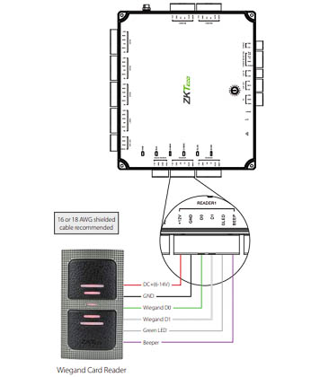
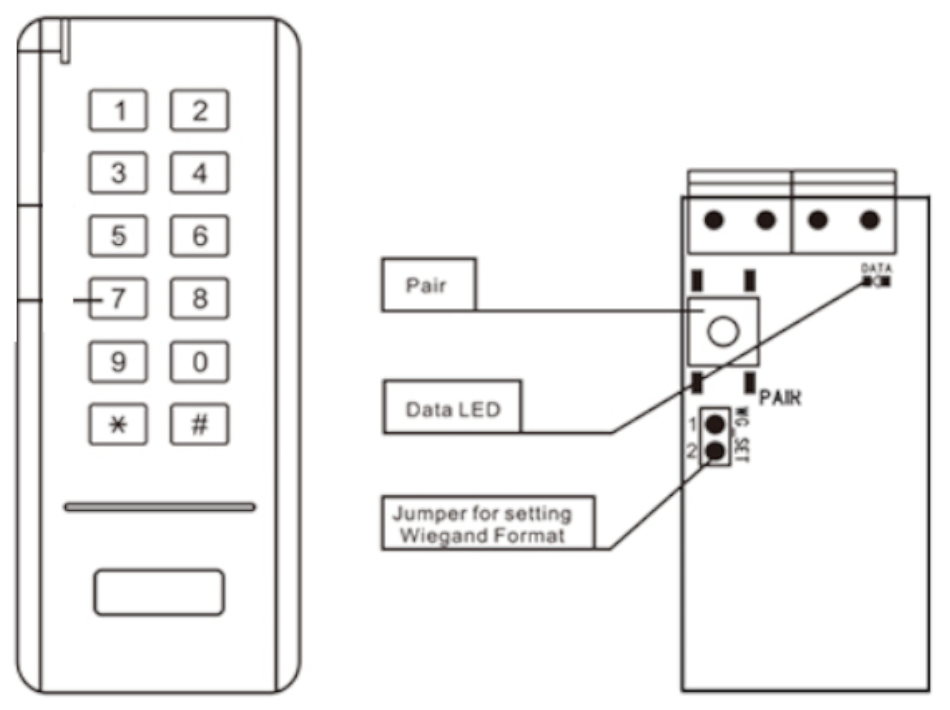
Below are the wiring diagram to connect the card reader using Wiegand Protocol: The Operation of LED is controlled by the Access Controller, the LED operation may vary depending on the Access Controller software. The normal behavior, the LED on card reader will turn Green to indicate that card is read and privileged. 1.
Access Control Card Reader Wiring Diagram. Variety of access control card reader wiring diagram. A wiring diagram is a streamlined traditional photographic representation of an electric circuit. It shows the components of the circuit as streamlined forms, as well as the power and signal connections in between the gadgets. A wiring diagram normally offers details regarding…
1.3 Wiring Diagram How to wire Card Reader via RS-485 protocol Description This article is to show how to wire Dahua Card Reader to Dahua Access Controller using RS-485 Protocol. An RS485 bus is capable of covering up to 1000m end to end, using twisted-pair cables.
See here for the Duet 3 Mainboard 6HC Wiring Diagram. A more detailed wiring guide will follow. Here is a photo showing a bench setup comprising a version 0.5 Duet 3 main board, Raspberry Pi 3B+, and one early prototype Duet 3 expansion board. Caution! Note the orientation of the 40-pin ribbon cable.
Lenel Card Reader Wiring Diagram. Wire Requirements. Inputs twisted pair per input, 30 ohms maximum. Outputs. 5 A 28 VDC. Reader Power Output Regulated Mode. mA maximum each. Lenel offers a Dual Reader Interface (DRI) module for access control between the Intelligent System Controller (ISC) and the card reader attached to the interface.
Taking attendance manually consumes more time. So, In this project we have designed RFID Based Attendance System using Arduino and RFID MFRC522 Module. In this system, each student is issued an RFID card as their id card and their attendance is marked when they touch their card to RFID reader.
Cable Conduit (Punch Hole for cables) Temper Switch InBio Pro Panel Heat Dissipation Grill Power Supply Backup Battery State Indicators Mounting Holes Inserting Panel to Rail Mounting Rail We recommend drilling the mounting plate screws into solid wood (i.e. stud/beam).
I will use our DX Series 2 Door Access control Board , a Proximity Card Reader , an electronic door strike (ACDS-DX1500SE), 22-8 wire and a power supply with at least 3 or 5 amps. In this article I will cover the steps to wire the electronic door strike and access control reader to the board and test the system.
The K501 is a single entry Access Controller with integrated 4 PIN keypad and card reader, housed in a strong Zinc. Alloy electroplated case, supports up to ...11 pages
The diagram below shows the wiring using an external power supply. Reader-Controller and the External Door Kit When the Isonas reader-controller is installed outside, the External Door Kit (EDK) is added to provide additional security. In this configuration, the reader-controller sends a coded message to the EDK located indoors.
access control card reader wiring diagram - Just What's Wiring Diagram? A wiring diagram is a sort of schematic which utilizes abstract pictorial icons to reveal all the affiliations of elements in a system.
Wiegand refers to the technology used in card readers and sensors. This system is a wired communication interface that operates between a reader and a controller. Typically, Wiegand technology is found in cards, fingerprint readers, or any other data-capturing devices. This is most commonly used in access control applications. The wire communication aspect of these …
The FB-4 provides four (4) individually fused outputs for modular system protection. A 2 amp fuse ... Request-to-Exit Push Bar, Keypad, Card Reader, Motion.8 pages
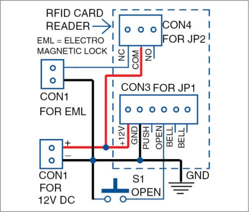
The block diagram of the access control system is shown in Fig. 1. It is built around a magnetic lock with mounting brackets, 12V SMPS /adaptor for power supply, access control device, exit push button, RFID tags and cables. It includes 3- and 6-pin connectors along with 3- and 6-wire cables to connect the access control device.
08.04.2019 · RFID Attendance System LCD Wiring Diagram. Testing the 16×2 LCD Display . 1. Now that the circuit has been set up let’s go ahead and test it to ensure that everything was wired correctly. To start, go ahead and clone the Adafruit CharLCD library that we will be utilizing for this project. If your display board uses the HD44780 controller, then it will work with no issues. To …
access control host panel. When the LED is controlled directly by the reader, the LED normal state is red, and indicates that the reader is ready to read an access card. The LED turns green when the access card is read and the message is transmitted to the Host system. When the reader is ready for another access card, the LED returns to red. The typical time the LED is …
Each reader port can accommodate a reader that utilizes TTL (D1/D0, Clock/Data), F/2F (standard or supervised) or 2-wire RS-485 device signaling (OSDP reader for example) and also provides tri-state LED control, and buzzer control (one wire LED mode only). Four Form-C relay outputs may be used for door strike control or alarm signaling.
The diagram below shows the general wiring layout for a Net2 plus ACU. Not all of the equipment shown needs to be installed on every door. For example, when using Timesheet it is only necessary to install a reader and the data connection.
Access_Control_Proximity_Setup(20160502).doc Page 7 of 21 Rev. 20160502 V. Additional Access Control Configurations Electric Door Strike (Normally Open Circuit) MagLock (Normally Closed Circuit) VI. Where to Place the Hardware The Proximity Card Reader or Wiegand Keypad should be mounted near the door. It does not need to
What is the wiring diagram for OSDP? If you're interested in having a more in-depth look at how it works, take a look at this OSDP protocol example diagram, which gives an insight into how to use it with existing Wiegand devices. This includes how to connect both a Peripheral Device (PD) or Access Control Unit (ACU), or both.
17.10.2021 · After I get done with the electronics case wiring diagram, I ... and generate signals on PINs to control stuff, but I do not plan on powering stuff off the Octopus Pro board that is considered optional equipment like LEDs, an endoscope or cameras. Since my Raspberry Pi (running Klipper) is the brains of this setup, I will be using a solid state drive to act as the disk …
Card Reader Wiring Diagram Cornick. 609xa Proximity Reader User Manual Hid Global. Access Cards And Readers Card. Mcas Wiring Details. Wiring Diagram Proximity Card Radio Frequency Identification Hid Global Reader Png Clipart Access Badge Angle. Avea Decorative Rfid Proximity Card Reader Audit Trail Rs232 Connection.
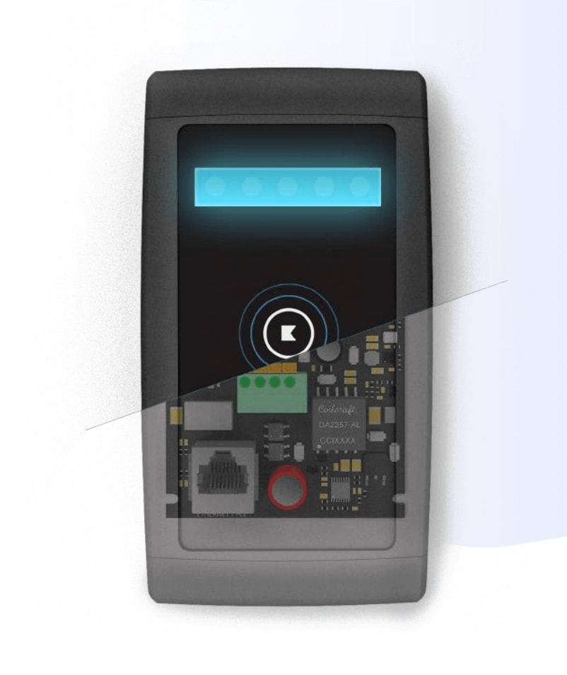
Door Access Control System Wiring Diagram Below is a visual representation of how to wire your access control system: CAT6 cables connect readers and controllers to the internet switch. Power is supplied to the door lock and the Kisi Pro Controller. Kisi wiring diagram Magnetic Lock Wiring Diagram
In an access control system, use Cat 5 to connect the ACU to the LAN (internet). To connect credential readers to the ACU, use 22 gauge 6 conductor shielded cables. Credential readers must be within a 500-foot distance from the ACU for the reader to work properly.
A wiring diagram is a straightforward visual representation of the physical connections and physical layout of your electrical system or circuit. It shows the way the electrical wires are interconnected and will also show where fixtures and components could be attached to the system.
2.2.1 Card reader technologies 7 2.2.2 Credentials technology 7 ... Room Access control hardware RS-485 Readers Wiegand Readers Wiring topology bus, ("chain") star Maximum cable length 1200m 100m Number of wires needed for the reader ... 2.2.3 Wiring for non-reader components







0 Response to "35 access control card reader wiring diagram"
Post a Comment