35 the er diagram represents the physical database as viewed by the end user
Generally, the high-level design is done in the ER model and implementation is done in the rel … View the full answer Transcribed image text: The entity relationship diagram (ERD) represents the database as viewed by the end user. The basis of an entity relationship diagram (ERD) which depicts the: Conceptual database as viewed by end user Database's main components - Entities - Attributes - Relationships Entity refers to the entity set and not to a single entity occurrence
Database Systems - Design, Implementation, and Management (9th Edition) Habib Adnan. Download PDF. Download Full PDF Package. This paper. A short summary of this paper. 15 Full PDFs related to this paper. READ PAPER. Database Systems - Design, Implementation, and Management (9th Edition) Download . Database Systems - Design, Implementation, and …
The er diagram represents the physical database as viewed by the end user
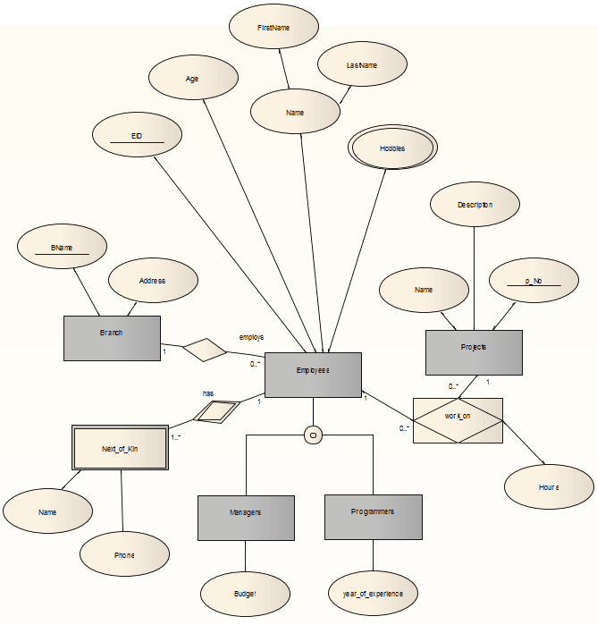
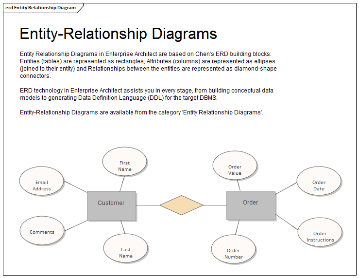
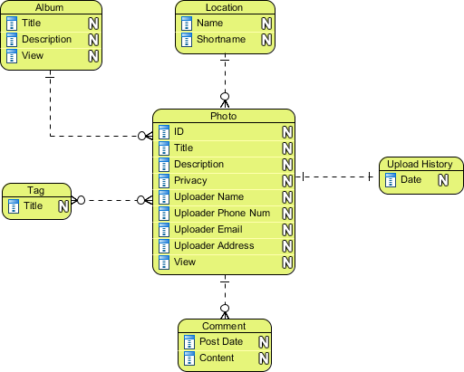
The entity relationship (ER) data model has existed for over 35 years. It is well suited to data modelling for use with databases because it is fairly abstract and is easy to discuss and explain. ER models are readily translated to relations. ER models, also called an ER schema, are represented by ER diagrams. ER modelling is based on two concepts: Dec 11, 2021 · ER Diagram stands for Entity Relationship Diagram, also known as ERD is a diagram that displays the relationship of entity sets stored in a database. In other words, ER diagrams help to explain the logical structure of databases. ER diagrams are created based on three basic concepts: entities, attributes and relationships. ER Diagrams contain different symbols that use rectangles to represent entities, ovals to define attributes and diamond shapes to represent relationships. Processing requirements are typically specified using natural language expressions or SQL commands along with the frequency of occurrence. Figure 1.2 (Step II.a) shows a possible ER model representation of the product/customer database in the mind of the end user. b. View integration.
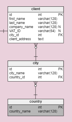
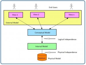
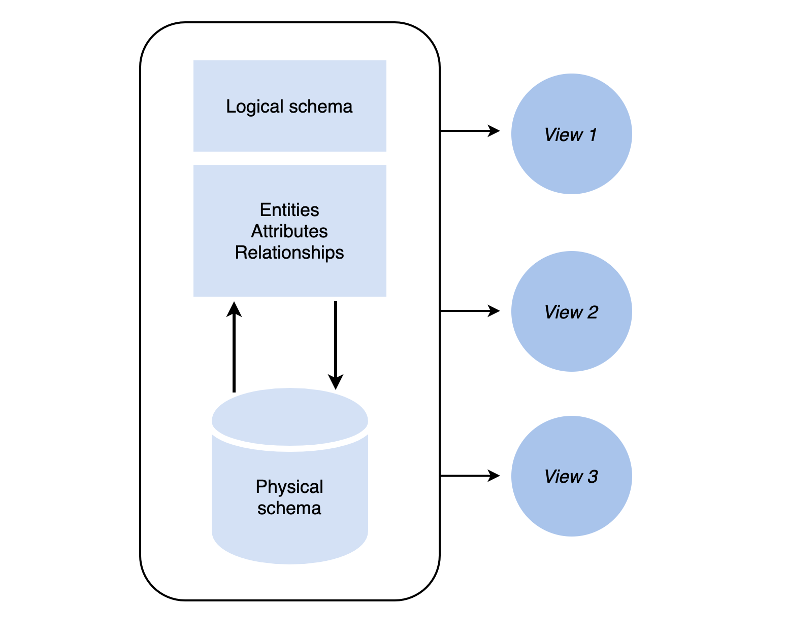
The er diagram represents the physical database as viewed by the end user. The physical model is simply the way the data is stored on disk. Each database vendor has its own way of storing the data. Figure 5.1. Data abstraction layers. Schemas. A schema is an overall description of a database, and it is usually represented by the entity relationship diagram (ERD). There are many subschemas that represent external ... Entity Relationship Diagram, also known as ERD, ER Diagram or ER model, is a type of structural diagram for use in database design. An ERD contains different symbols and connectors that visualize two important information: The major entities within the system scope, and the inter-relationships among these entities. Define each of the following database terms Relation Primary key Foreign key Referential integrity Field Data type Null value 9.29.2 Discuss the role of designing databases in the analysis and design of an information system Learn how to transform an entity-relationship (ER) Diagram into an equivalent set of well-structured relations The physical data model is the most granular level of entity-relationship diagrams, and represents the process of adding information to the database. Physical ER models show all table structures, including column name, column data type, column constraints, primary key, foreign key, and relationships between tables.
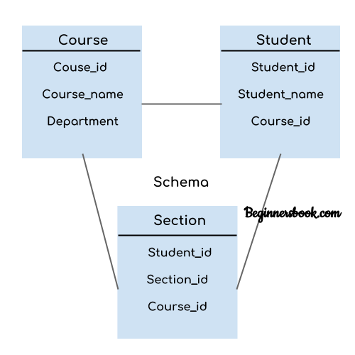
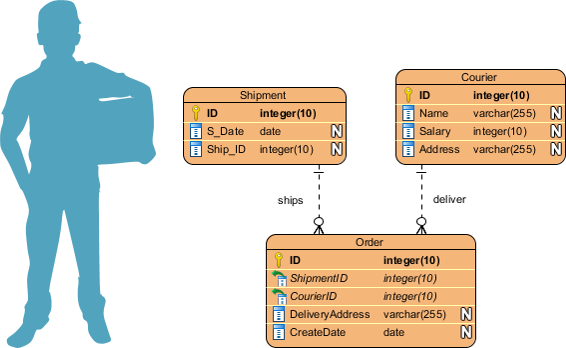
Entity-relationship (ER) diagrams are the blueprints for database applications in OLTP systems. The process of creating ER diagrams is well documented and involves: Identifying database entities (tables) Defining entity attributes (columns) Identifying unique row identifiers (keys) Defining relationships between entities The entity relationship diagram erd represents the. This preview shows page 2 - 4 out of 5 pages. (9) The entity relationship diagram ( ERD ) represents the _____ database as viewed by the end user. (a) condensed (b) physical (c) logical (d) conceptual. (10) The _____ notation of entity - relationship modelling can be used for both conceptual ... The physical database schema represents how data is stored on disk storage or data target. Physical schema is the lowest form of abstraction with regards to the schema. ... which generally describes end-user interaction with database systems. At the view level, a user can interact with the system using an interface. ... In an ER diagram, draw a ... Question 35 1 / 1 point The ERD is used to graphically represent the ____ database model. Question options: conceptual physical logical condensed Question 36 1 / 1 point Relationship strength depends on how the primary key of the related entity is formulated, while the relationship ____________________ depends on how the business rule is written.
We also do not have a database of previously written papers. All our papers are written from scratch according to the client’s instructions. We never send published papers to clients nor do we publish the papers after sending them to our clients. Do I have to reference you in my work. Whether to reference us in your work or not is a personal decision. If it is an academic paper, … DBMS MCQ. This section of interview questions and answers focuses on "Database Management System". One shall practice these interview questions to improve their concepts for various interviews such as campus interviews, walk-in interviews, company interviews, placements, entrance exams and other competitive exams. ER-Diagram is a pictorial representation of data that describes how data is communicated and related to each other. Any object, such as entities, attributes of an entity, sets of relationship, and other attributes of relationship, can be characterized with the help of the ER diagram. Entities: They are represented using the rectangle-shaped box. The Entity-Relationship (ER) model was originally proposed by Peter in 1976 as a way to unify the network and relational database views. Simply stated, the ER model is a conceptual data model that views the real world as entities and relationships. A basic component of the model is the Entity-Relationship diagram, which is used to visually ...
E-R Model Case Studies 1 : Suppose you are given the ...
applications programmer, and the end user • End users have different views and needs for data • Data model organizes data for various users • Data model is a conceptual model -an abstraction • It's a graphical collection of logical constructs representing the data structure and relationships within the database.
Explaining an ER Diagram, With Steps and Use Cases ...
Database Entity Relationship Diagrams 1. Overview The data model presented in this annex represents a logical view of the database design for the ITL. It does not include all the entities needed for the ITL administrator application, which might include additional report and job catalogs. The logical data model may also include entities and
Blog - Work with entity relationship table shapes in diagrams.net
The entity relationship diagram (ERD) represents the _____ database as viewed by the end user. Select one: a. logical b. condensed c. conceptual d. physical. conceptual. The entity relationship model uses the associative entity to represent a(n) _____ relationship between two or more entities.
Chapter 8 The Entity Relationship Data Model – Database ...
the end user's view of the data environment External Schema The specific representation of an external view; the end user's view of the data environment Conceptual model represents a global view of the entire database by the entire organization Software independence the model does not depend on the DBMS software used to implement the model
Instance and schema in DBMS
Use only the basic ER model here, that is, entities, relationships, and attributes. Be sure to indicate any key and participation constraints. Answer 2.3 The ER diagram is shown in Figure 2.1. Exercise 2.4 A company database needs to store information about employees (iden-ti ed by ssn,withsalary and phone as attributes); departments (identi ed ...
Entity Relationship Diagrams (ERDs) | Enterprise Architect ...
The entity relationship diagram (ERD) represents the _____ database as viewed by the end user. A. M:N 18. An entity is said to be _____-dependent if it can exist in the database only when it is associated with another related entity occurrence.

Advanced Database Management System - Tutorials and Notes ...
Entity Relationship Diagram (ERD) represents the _____ database as viewed by the end user. a. condensed b. physical c. logical d. conceptual

Entity-Relationship Diagram Symbols and Notation | Lucidchart
The first is an entity-relationship diagram which represents the data strucures in a pictorial form. ... database developer to construct the physical database. ... to communicate to the end user ...
5 Database Design Schema Examples: Critical Practices and ...
The Entity Relationship Model. Widely accepted standard for data modeling . Introduced by Chen in 1976. Graphical representation of entities and their relationships in a database structure. Entity relationship diagram (ERD) Uses graphic representations to model database components. Entity is mapped to a relational table. Database Systems, 9th ...

What is a Logical Data Model? | TIBCO Software
This means that designers can use ER diagrams to easily communicate with developers, customers, and end users, regardless of their IT proficiency. Second, ER diagrams are readily translatable into relational tables which can be used to quickly build databases.

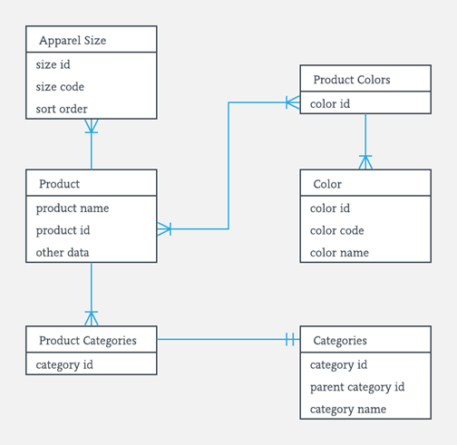
Convert ER diagram to relational tables example
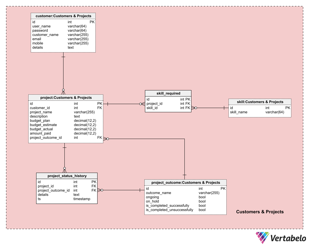
An Entity Relationship Diagram (ERD) is a type of diagram that lets you see how different entities (e.g. people, customers, or other objects) relate to each other in an application or a database. They are created when a new system is being designed so that the development team can understand how to structure the database.

Create a diagram with Chen's database notation
Customers-Suppliers-Products Entity-Relationship Diagram Rectangles represent entity types Ellipses represent attributes ... Empty Circle at the end of a line linking an attribute to an entity type represents an optional (null) attribute (not mentioned in textbook) Not in the above diagram, but later in examples: Double Ellipses represent multi ...

DBMS Schemas: Internal, Conceptual, External
Processing requirements are typically specified using natural language expressions or SQL commands along with the frequency of occurrence. Figure 1.2 (Step II.a) shows a possible ER model representation of the product/customer database in the mind of the end user. b. View integration.

ER Diagram (ERD) - Definition & Overview | Lucidchart
Dec 11, 2021 · ER Diagram stands for Entity Relationship Diagram, also known as ERD is a diagram that displays the relationship of entity sets stored in a database. In other words, ER diagrams help to explain the logical structure of databases. ER diagrams are created based on three basic concepts: entities, attributes and relationships. ER Diagrams contain different symbols that use rectangles to represent entities, ovals to define attributes and diamond shapes to represent relationships.

quiz3cis305.docx - Question 1 10 out of 10 points The ER ...
The entity relationship (ER) data model has existed for over 35 years. It is well suited to data modelling for use with databases because it is fairly abstract and is easy to discuss and explain. ER models are readily translated to relations. ER models, also called an ER schema, are represented by ER diagrams. ER modelling is based on two concepts:
Difference between DFD and ERD - GeeksforGeeks
Entity Relationship Diagram | Enterprise Architect User Guide
Module 2 - Relational Diagram for Data Analysis - ER & SQL ...

What is Entity Relationship Diagram (ERD)?
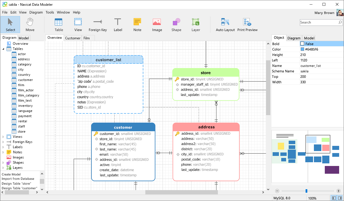
Navicat Data Modeler | Supreme Database Modeling and Design Tool

Conceptual Data Modeling - an overview | ScienceDirect Topics

Logical Data Model - an overview | ScienceDirect Topics
What is Entity Relationship Diagram (ERD)?
Navicat Data Modeler | Supreme Database Modeling and Design Tool
Explaining an ER Diagram, With Steps and Use Cases ...

Entity Relationship Diagram - an overview | ScienceDirect Topics
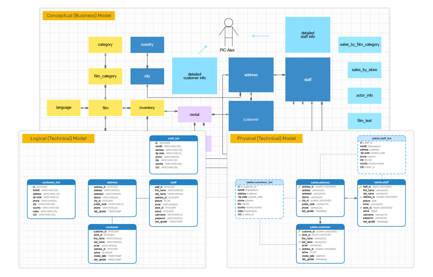
Conceptual, Logical and Physical Data Model

Database Life Cycle - an overview | ScienceDirect Topics

exam question 1 how to draw Entity Relationship Diagram ...

ER Diagram (ERD) Tool | Lucidchart

Three Level Database Architecture
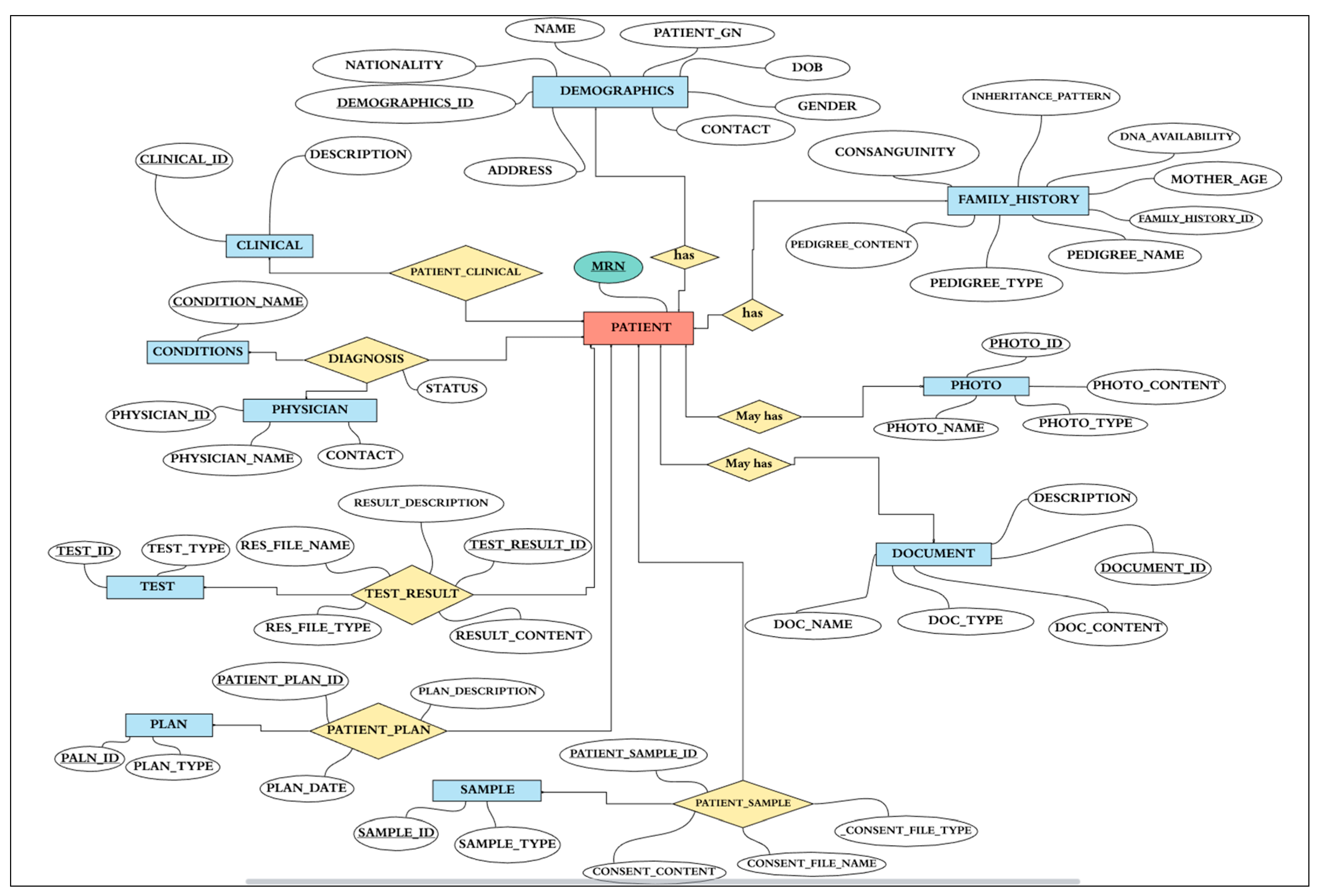
Healthcare | Free Full-Text | G3DMS: Design and ...

What is Entity Relationship Diagram (ERD)?
ER Diagram: Entity Relationship Diagram Model | DBMS Example

quiz3cis305.docx - Question 1 10 out of 10 points The ER ...
0 Response to "35 the er diagram represents the physical database as viewed by the end user"
Post a Comment