35 pv diagram problems and solutions
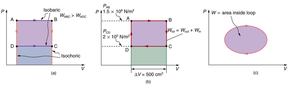
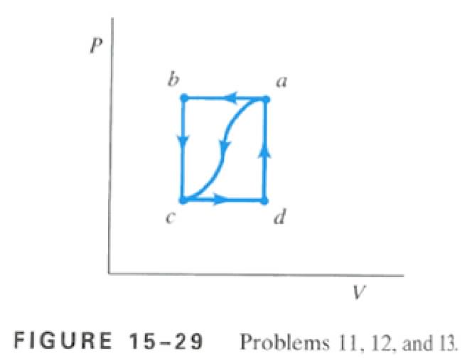
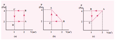
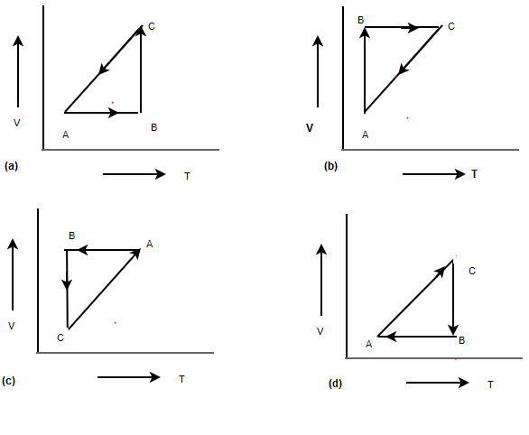
The PV diagrams for a thermodynamical system is given in the figure below. Calculate the total work done in each of the cyclic processes shown. Solution In the case (a) the closed curve is anticlockwise. So the net work done is negative, implying that the work done on the system is greater than the work done by the system. The solutions like superheating of steam are employed to overcome these problems. So, to overcome the losses and get more net power output some variations are adopted in the Rankine cycle. Some variations are discussed below, like. Rankine cycle with reheat; Rankine cycle with regeneration; Rankine Cycle with Reheat
Jan 24, 2022 · EEP - Electrical engineering portal is study site specialized in LV/MV/HV substations, energy & power generation, distribution & transmission

Pv diagram problems and solutions
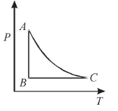
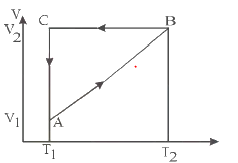
PV diagrams were originally called indicator diagrams. They were developed in the 18 th century as tools for understanding the efficiency of steam engines. It was developed by James Watt and John Southern. PV diagrams can be used to estimate the net work performed by a thermodynamic cycle. The net work is the area enclosed by the PV curve in ... PV of a deferred annuity = $5,550.18 / 1.04 = $5,336.71 d) three years from today. PV of a deferred annuity = $5,550.18 / 1.042 = $5,131.45 e) four years from today. PV of a deferred annuity = $5,550.18 / 1.043 = $4,934.09 Solutions to Time Value of Money Practice Problems 4 Solution - drawing the diagram a) The VT diagram shows: In the segment AB the volume of the gas is directly proportional to the temperature. This means that in this phase the pressure is constant, it is an isobaric process. In the pV diagram it is represented by a horizontal line.
Pv diagram problems and solutions. - Something you see a lot when doing thermodynamics especially problems involving the first law are what are called PV Diagrams. Now, the P stands for Pressure and the V stands for Volume. And this gives you a diagram of what the pressure and volume are in any given instant. Below is a Pressure-Volume diagram. In "geek-speak" it is called a "PV diagram." Notice that is looks like a graph, but it's not. It's a diagram. This diagra... 780 mol of a gas expand isothermally as shown in the PV diagram below. How much work is done by the gas? Learn this topic by watching PV Diagrams & Work Concept Videos. All Physics Practice Problems PV Diagrams & Work Practice Problems. PV diagram. A thermodynamic process is a process by which a thermodynamic system goes from one state of equilibrium to another. Although the child in the upper figure can hardly be considered a system in equilibrium, the example is useful to illustrate what happens in a thermodynamic system. Initially it is in a state 1 and, after exchanging ...
Isobaric thermodynamics processes - problems and solutions. 1. PV diagram below shows an ideal gas undergoes an isobaric process. Calculate the work is done by the gas in the process AB. 2. What is difference of the work is done by the gas in process AB and process CD…. SOLAR ELECTRICITY: PROBLEM, CONSTRAINTS AND SOLUTIONS The United States generates over 4,110 TWh of electricity each year, costing $400 billion and emitting 2.5 billion metric tons of carbon dioxide (Yildiz, 2010). Additionally, the United States' total electricity consumption has increased annually by an average of one percent over the past Work & PV Diagrams. Q. Work Done by the Lungs. The graph (Figure 1) shows a pV-diagram of the air in a human lung when a person is inhaling and then exhaling a deep breat... Solved • Jul 14, 2020. Work & PV Diagrams. Q. A) Find w12, the work done on the gas as it expands from state 1 to state 2.Express the work done in terms of Po and VoB ... [mirror download link : https://goo.gl/o24NN ] Solving problems in school work is the exercise of mental faculties, and examination problems are usually picked from the problems in school work. Working out problems is a necessary and important aspect
Biblioteca en línea. Materiales de aprendizaje gratuitos. 1000 Solved Problems in Classical Physics Ahmad A. Kamal 1000 Solved Problems in Classical Physics An Exercise Book 123 Dr. Ahmad A. Kamal Silversprings Lane 425 75094 … Physics questions and answers. Exercise 19.13 - Enhanced - with Solution The pV diagram in the figure (Figure 1) shows a process abc involving 0.540 mol of an ideal gas. You may want to review (Pages 623 - 628). For related problemsolving tips and strategies, you may want to view a Video Tutor Solution of A cyclic process. 1. PV diagram below shows an ideal gas undergoes an isothermal process. Calculate the work is done by the gas in the process AB. Solution Work done by a gas is equal to the area under the PV curve AB = triangle area + rectangle area W = [½ (8 x 10⁵–4 x 10⁵)(3-1)] + … Isothermal thermodynamic processes – problems and solutions Read More » Solutions to problems P1A.2 Perfect gas behaviour indicates that pV ∝ T, where T is the absolute tempera-ture. In terms of the temperature θ in N, T is written T = θ + θ 0 , where θ 0 is the absolute temperature of zero on the N scale.
For the P - V diagram given for an ideal gas, out of the ...
look at PV diagrams. A PV diagram is a graph of Pressure as a function of Volume. There are four different situations that you can expect to see shown in PV diagrams: 1. Isobaric: the gas is held at a constant pressure 2. Isochoric: the gas is held at a constant volume 3. Isothermal: the gas is held at a constant temperature 4.

Example 7E - 4: Performance of an Ideal Gas Cycle
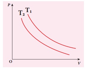
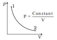
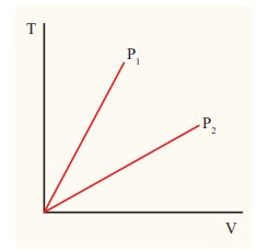
Examples and Problems Reading: Elements Ch. 1-3. Physics 213: Lecture 3, Pg 2 ... Lecture 3, p 3 For an ideal gas at constant T, p is inversely proportional to the volume. Ideal Gas p-V, p-T Diagrams NkT p V = increasing T Volume Pressure p vs V at various constant T's 0 Pressure Temperature 0 ... Solution Consider the two systems shown to ...
PV Diagrams
Homework Statement The PV diagram below (I will describe it) shows a cycle for 4.87moels of an ideal gas. The path ab is along an isothermal line. Pressure is in atm and volume in m3 Point a: (.08, 6) Point b: (.24,2) Point c: (.08, 2) Find the ideal and the actual efficiency of...

The figure below shows the PV cycle for a heat engine that uses 2 moles of a monoatomic gas. The initial temperature is Ta = 300 K. The engine runs through 3 process: an isotherm, an isobar, and an
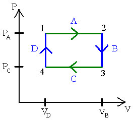
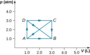
Problems practice. One mole of an ideal, monatomic gas runs through a four step cycle. All processes are either isobaric or isochoric. The pressure and volume of the gas at the extreme points in the cycle are given in the table below. Sketch the PV graph of this cycle. Determine the temperature at state A, B, C, and D.

Chapter 3d - The First Law - Closed Systems - Otto Cycle ...
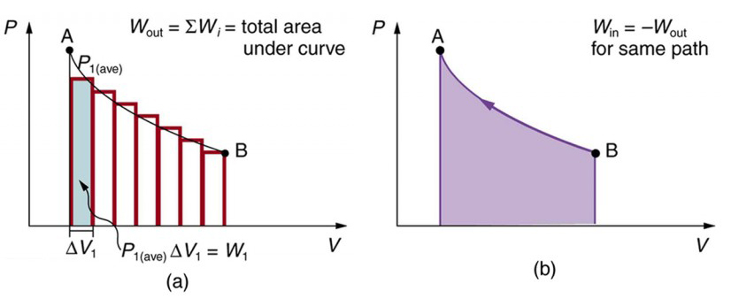
PV Diagrams were particularly useful for evaluating boundary work. The amount of boundary work done on or by the system as a process moves the system from state 1 to state 2 is the area underneath the path between states 1 and 2 on a PV Diagram. In the remainder of this lesson, you will learn how and why.
PV Graph and First Law of Thermodynamics
First law of thermodynamics problem solving. PV diagrams - part 1: Work and isobaric processes. PV diagrams - part 2: Isothermal, isometric, adiabatic processes. Second law of thermodynamics. Next lesson. Thermochemistry.
The First Law of Thermodynamics and Some Simple Processes ...
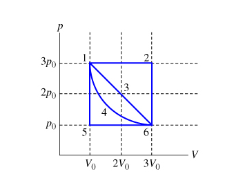
A cyclic Process is shown in the given below p-T digram. Which of the following curves shows the same process in p-V diagram Solution (a) This can be easily solved with ideal Gas equation P V =nRT P V = n R T At constant T, P is inversely proportional to V .An isotherm Curve At constant Pressure, Volume is directly proportional to T.
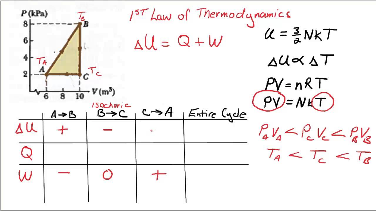
1st law
Work and PV Diagrams. GOAL Calculate work from a PV diagram. PROBLEM Find the numeric value of the work done on the gas in (a) Figure 12.4a and (b) Figure 12.4b. STRATEGY The regions in question are composed of rectangles and triangles.Use basic geometric formulas to find the area underneath each curve. Check the direction of the arrow to determine signs.
Problem set
Problem: Solution: Reasoning: The process is isobaric. For an isobaric process W = P(V 2 - V 1). Details of the calculation: W = P(V 2 - V 1) = P(2V 1 - V 1) = PV 1 = 151500 Pa*4 m 3 = 606000 J. (The work is the area under curve in the PV diagram. ΔV is positive because the gas expands, and therefore the work W done by the gas is positive ...
The First Law of Thermodynamics and Some Simple Processes ...
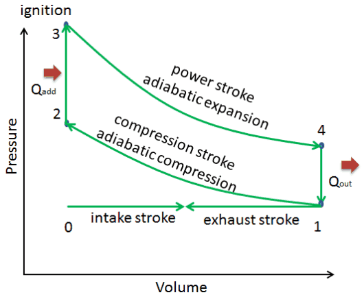
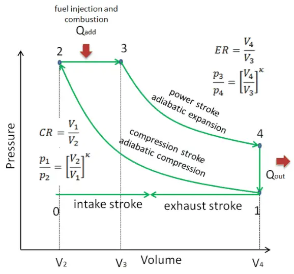
pV diagram of Otto Cycle. The area bounded by the complete cycle path represents the total work that can be done during one cycle. In this example let assume an Otto cycle with compression ratio of CR = 9 : 1. The intake air is at 100 kPa = 1 bar, 20 °C, and the volume of the chamber is 500 cm³ prior to the compression stroke.
Solved Example Problems for Thermodynamic Processes
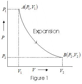
EXAMPLE 8.15 (PV diagram) A gas expands from volume 1m3 to 2m3 at constant atmospheric pressure. (a) Calculate the work done by the gas. (b) Represent the work done in PV diagram. Solution (a) The pressure P = 1 atm = 101 kPa, V f =2 m 3 and V 1 = 1m 3. From equation (8.17) W = Since P is constant. It is taken out of the integral.
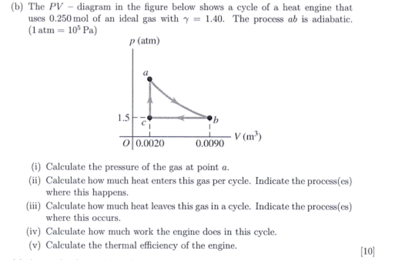
Solved (b) The PV -diagram in the figure below shows a cycle ...
Algebra -> Customizable Word Problem Solvers -> Misc-> SOLUTION: Draw the P-V diagram for a reversible, isothermal compression of exactly one mole of gas from 2.0 L to 0.50 L at a temperature of 290. K.
Otto Cycle - Problem with Solution | nuclear-power.com
Solar system problems may have complex causes, but solving them is usually routine. It just takes experience to get started off on the right foot. Keeping track of your system's performance is an easy, effective troubleshooting solution. So is staying in touch with a specialist.
Solved Example Problems for Thermodynamics Cyclic processes
Force of gravity and gravitational field - problems and solutions. In the pV diagram it is represented by a horizontal line. All material given in this website is a property of Isothermal thermodynamic processes - problems and solutions. look at PV diagrams. In a cyclic Process,heat is absorbed by a gas when the work done by it is positive.
The First Law of Thermodynamics and Some Simple Processes ...
Hybrid power are combinations between different technologies to produce power.. In power engineering, the term 'hybrid' describes a combined power and energy storage system.. Examples of power producers used in hybrid power are photovoltaics, wind turbines, and various types of engine-generators – e.g. diesel gen-sets.. Hybrid power plants often contain a renewable …
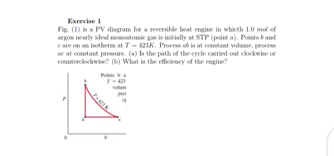
Answered: Exercise 1 Fig. (1) is a PV diagram for… | bartleby
This physics video tutorial provides a basic introduction into PV diagrams. It explains how to calculate the work done by a gas for an isobaric process, iso...

Chapter 3a - The First Law - Closed Systems - Energy (updated ...
Solution - drawing the diagram a) The VT diagram shows: In the segment AB the volume of the gas is directly proportional to the temperature. This means that in this phase the pressure is constant, it is an isobaric process. In the pV diagram it is represented by a horizontal line.
P-V Diagram Problems and Solutions
PV of a deferred annuity = $5,550.18 / 1.04 = $5,336.71 d) three years from today. PV of a deferred annuity = $5,550.18 / 1.042 = $5,131.45 e) four years from today. PV of a deferred annuity = $5,550.18 / 1.043 = $4,934.09 Solutions to Time Value of Money Practice Problems 4
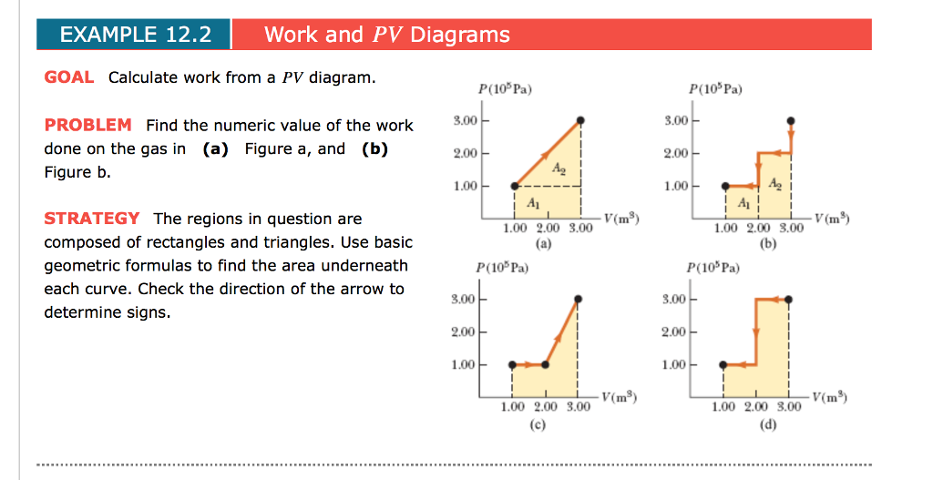
Solved EXAMPLE 12.2 Work and PV Diagrams GOAL Calculate work ...
PV diagrams were originally called indicator diagrams. They were developed in the 18 th century as tools for understanding the efficiency of steam engines. It was developed by James Watt and John Southern. PV diagrams can be used to estimate the net work performed by a thermodynamic cycle. The net work is the area enclosed by the PV curve in ...
Chapter 3 The First Law of Thermodynamics: Closed Systems The ...
Solved One important use for pV diagrams is in | Chegg.com
Work, Heat, and Internal Energy – University Physics Volume 2

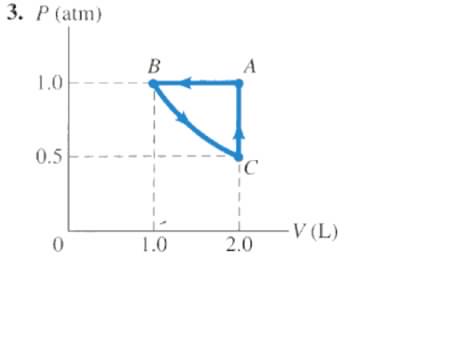
Work Done in a Cyclic Process (Triangle on PV Diagram)

Isobaric Thermodynamics Processes Problems and Solutions | PDF

Isothermal thermodynamic processes – problems and solutions ...
Problem set
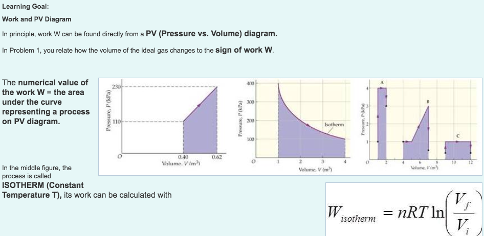
Solved Learning Goal Work and PV Diagram In principle, work ...
P-V Diagram Problems and Solutions

P1 1st pv-diagram problem and solution
P-V Indicator Diagram with solved Examples
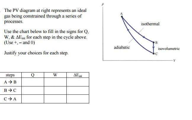
Solved The PV diagram at right represents an ideal gas being ...
Solved Example Problems for Isobaric process - Thermodynamics
Diesel Cycle – Problem with Solution | nuclear-power.com
P-V Indicator Diagram with solved Examples
P-V Diagram Problems and Solutions
0 Response to "35 pv diagram problems and solutions"
Post a Comment