36 consider the circuit in the diagram below, in which r = 13 ω.
Series RLC Circuit — Collection of Solved Problems The circuit is connected to an AC voltage source with amplitude 25 V and frequency 50 Hz. Determine the amplitude of electric current in the circuit and a phase difference between the voltage and the current. cpb-ap-se2.wpmucdn.com › learnElectricity – Exam type questions - St Leonard's College Ω. A battery of emf 6 volt is connected across 0.30 m of resistance wire of diameter 1.0 mm. A current of 0.5 ampere flows through the wire. Question 13 (1984 Question 59) What current will flow if this wire is replaced by 1.20 m of the same wire? A circuit consists of a 12 volt battery and two 4 ohm resistors connected in series. Draw the ...
5. Application of ODEs: Series RL Circuit An RL circuit has an emf of 5 V, a resistance of 50 Ω, an inductance of 1 H, and no initial current. In the two-mesh network shown below, the switch is closed at t = 0 and the voltage source is given The voltage source is given by V = 30 sin 100t V. Find the mesh currents i1 and i2 as given in the diagram.
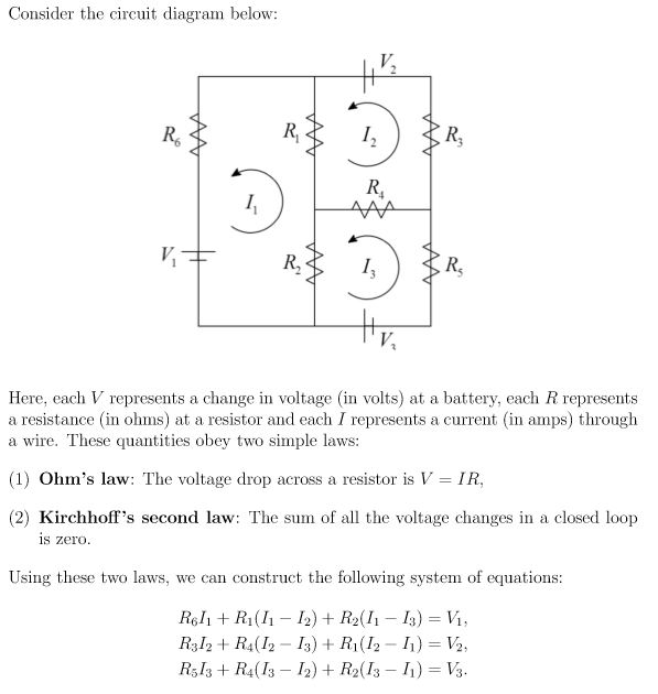
Consider the circuit in the diagram below, in which r = 13 ω.
PDF Recitation 6 13 looks like a Kirchho's loop rule involving only branches 1 and 2. The rst term −(220Ω)I1 looks like a V = IR resistor drop in the direction of the current on branch 1, so let's add a 220Ω resistor to branch 1. Because the voltage drops in our loop...21 and 23 is pretty straightforward. Consider the circuit. Consider the circuit shown in the figure below. - Brainly.com We get it: you didn't come here for ads. But ads help us give you free access to Brainly. Please consider whitelisting us! PDF Circuits Worksheet In which circuit below would the lamp operate correctly when switch S is closed? It would only operate in C. In A and D, closing the switch would introduce a pathway of zero resistance. ALL of the current would go down the path of no resistance leaving NO current passing through the lamp...
Consider the circuit in the diagram below, in which r = 13 ω.. Consider The Circuit In The Diagram Below In Which R 13 ω Solved In The Circuit Given Below R 13 W Using Mesh An. Openstax College Physics Ch21 Circuits And Dc Instruments Top Hat. Consider The Following Circuit Diagram If R1 R2 R3 R4 R5 3 Ohm. Calculate The Potential Difference Between Points A And B In The. Circuit Analysis and Design Find Ix from the diagram in Fig. Exercise 2-13 The circuit in Fig. E2-13 is called a resistive bridge. How does Vx = (V3 −V2) vary with the value of potentiometer R1? Solution: The circuit drawn in Multisim is shown below. Note: The expression entered into the ABM CURRENT source was V(foo)... PDF Lesson -13 | Gate Drive circuit for three phase fully controlled converter However, considerable simplification in the expression of ia can be obtained if i0 is replaced by its average value I0. This approximation will be valid 13.3 shows the circuit connection and wave forms in the inverting mode of operation where the load current has been assumed to be continuous and... Why does the overall resistance of a circuit decrease as the... - Quora In the diagram below there are 3 resistors connected in series.. The rate at which charge flows through a circuit is known as the CURRENT. In a parallel circuit, this current splits up among the various branches and then travels through them.
Physics Tutorial: Parallel Circuits Consider the circuit diagram below and its corresponding electric potential diagram. As shown in the electric potential diagram, positions A, B, C, E and G are all at a high electric potential. A single charge chooses only one of the three possible pathways; thus at position B, a single charge will move... PDF Chapter 2: Circuit Elements In Circuit Analysis we will consider planar circuits only. Many of the techniques we learn here cannot be applied to non-planar All node voltages must be labeled just as they are in the diagram above. In the circuit below the dependent source is connected between two non-reference essential nodes. Parallel Resistors Circuit and Current Divider Simple Circuit 2 Parallel Circuit Diagram. 3 Formula for Parallel Resistor. Consider the circuit in Figure.(1) For parallel circuit example let us see the circuit below and try to find all the currents This is known as the principal of current division, and the circuit in Figure.(1) is known as current divider. 1. In the circuit below, which meter is not correctly connected? 2. In the circuit below, n charge carriers pass the point P in a time t. Each charge carrier has To view this video please enable JavaScript, and consider upgrading to a web browser that supports 4 4.The diagrams below show combinations X, Y and Z of three resistors, each resistor having the...
Electrical Engineering Recent Questions | Chegg.com 13 Va Vsı = 7 V R1 R3 Vs2 = 5 V Vsi 124 Vs2 R = 680 Ω R2 R2 = 390 S2 R3 = 910 22 Table 4.1 Calculated Data Vsi Active Q: = In the circuit below, a resistor with a constant resistance of R4 = 60 22 and a resistor with a temperature dependent resistance of 1 can be simplified to the circuit in Fig. RLC Circuits (Alternating Current) | Brilliant Math & Science Wiki Considering the flow of a time-dependent current. II. I through the circuit shown below enables us Phasor diagrams are such diagrams that represent these scalar quantities with a direction and help Quite basically, such a device can be viewed to consist of an LCR circuit in it. When it receives an... Consider The Circuit In The Diagram Below In Which R 13 ω The arrows in the diagram could represent the release of 1 atp from a chloroplast carrying out photosynthesis 2 oxygen from a mitochondrion... › accircuits › phasorsPhasor Diagram and Phasor Algebra used in AC Circuits Generally, when constructing a phasor diagram, angular velocity of a sine wave is always assumed to be: ω in rad/sec. Consider the phasor diagram below. Phasor Diagram of a Sinusoidal Waveform As the single vector rotates in an anti-clockwise direction, its tip at point A will rotate one complete revolution of 360 o or 2π representing one ...
Consider the circuit diagram below 尼 I. R, R, Here, | Chegg.com
PDF Exercises on Static Circuits The circuit below shows a simple voltage regulator based. on a zener diode with zener voltage vz. 10. Reected resistance seen through a transformer. Consider the circuit shown below: PSfrag replacements. The schematic diagram below shows a general model of an (ideal, linear) amplier.

11.2 Ohm's Law | Electric circuits | Siyavula
en.wikipedia.org › wiki › LC_circuitLC circuit - Wikipedia The numerator implies that in the limit as ω → ±ω 0, the total impedance Z will be zero and otherwise non-zero. Therefore the series LC circuit, when connected in series with a load, will act as a band-pass filter having zero impedance at the resonant frequency of the LC circuit. Parallel circuit
Chapter 11 Circuits
Consider four circuits shown in the figure below. In which circuit... In which circuit power dissipated is highest? > Refer to teh circuit shown. What will be the total power dissipation in the circuit if P is the power dissipated in R1 ? It is given that R2 =4R1 and R3 =12R1.
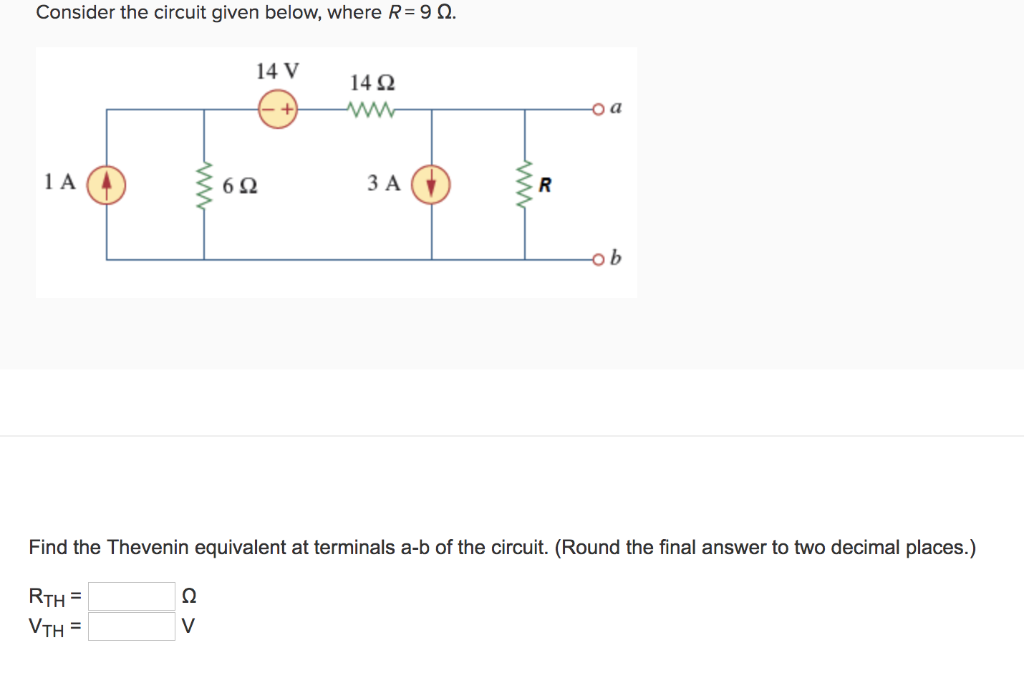
Solved Consider the circuit given below, where R-9 Ω. 14V ...
› cms › lib4CIRCUITS WORKSHEET R - Livingston Public Schools 10) Determine the resistance of resistor R shown in the diagram. Questions 11 through 13 refer to the following: A 3.0-ohm resistor, an unknown resistor, R, and two ammeters, A 1 and A 2, are connected as shown below with a 12-volt source. Ammeter A 2 reads a current of 5.0 amperes. 11) Determine the equivalent resistance of the circuit shown.

Current through resistor in parallel: Worked example
Series RLC Circuit and RLC Series Circuit Analysis The phasor diagram for a series RLC circuit is produced by combining together the three individual phasors above and adding these voltages vectorially. The phase angle, θ between the source voltage, VS and the current, i is the same as for the angle between Z and R in the impedance triangle.
RL Series Circuit Analysis (Phasor Diagram, Examples ...
R-L-C circuit As we shall see below, a purely inductive circuit corresponds to infinite capacitance C = ∞ and zero resistance R = 0 . Figure 12.2.3 A purely inductive circuit We would Figure 12.2.5 A purely capacitive circuit We would like to find the current in the circuit, 12-8. 13. Using the phasor representation, Eq.
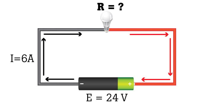
What is Ohm's Law? | Fluke
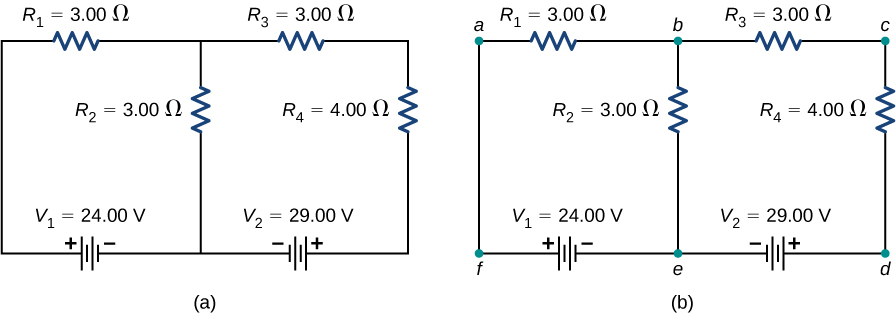
For the circuit shown in the figure, calculate (a) the current in the... For the circuit shown in the figure, calculate (a) the current in the 2.00-Ω resistor and (b) the potential difference between points a and b, ΔV = Vb - Va.
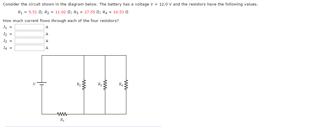
Solved Consider the circuit shown in the diagram below. The ...
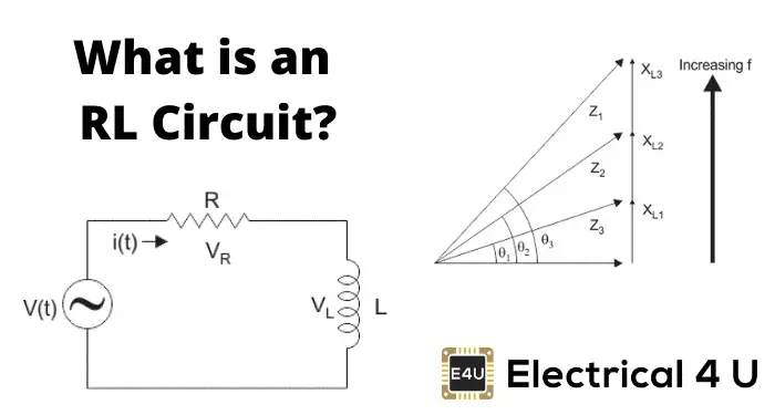
› accircuits › acAC Inductance and Inductive Reactance in an AC Circuit May 17, 2021 · Consider the circuit below were a pure non-inductive resistance, R is connected in series with a pure inductance, L. Series Resistance-Inductance Circuit In the RL series circuit above, we can see that the current is common to both the resistance and the inductance while the voltage is made up of the two component voltages, V R and V L .

AC Resistance and Impedance in an AC Circuit
Network Theory - Nortonâs Theorem Step 1 − Consider the circuit diagram by opening the terminals with respect to which the Norton's equivalent circuit is to be found. The Norton's equivalent circuit corresponding to the above Thevenin's equivalent circuit is shown in the following figure.

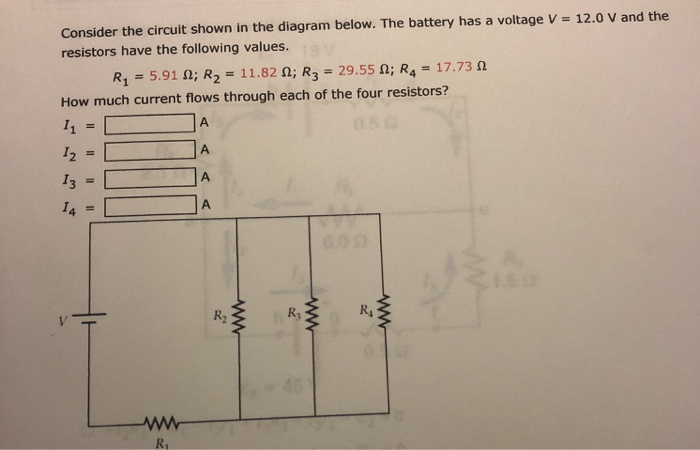
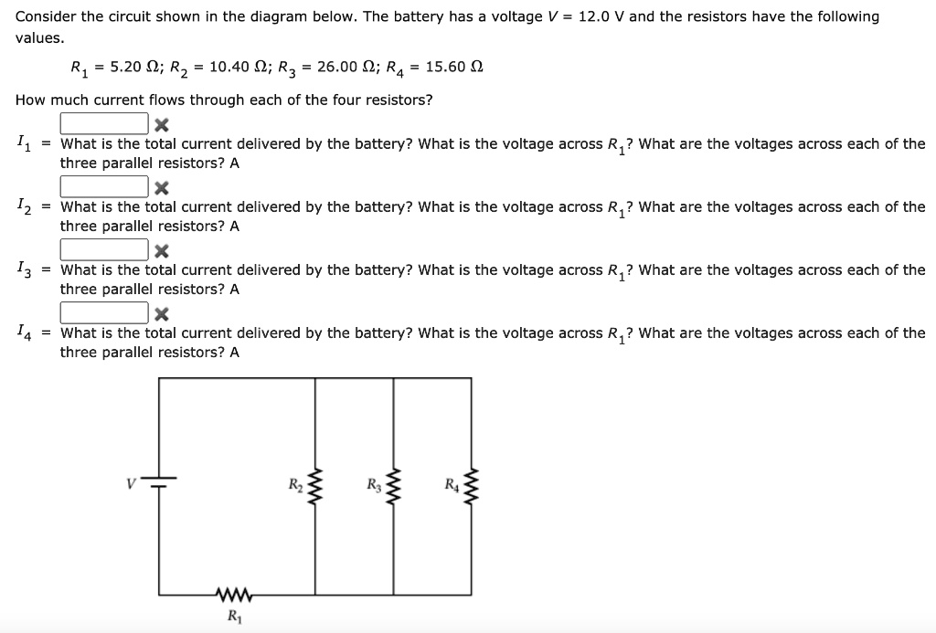
Consider the circuit shown in the diagram below. The battery ...
RLC Series AC Circuits | Physics Draw the circuit diagram for an RLC series circuit. Explain the significance of the resonant frequency. The crux of the analysis of an RLC circuit is the frequency dependence of XL and XC, and the effect they have on the phase of voltage versus current (established in the preceding section).
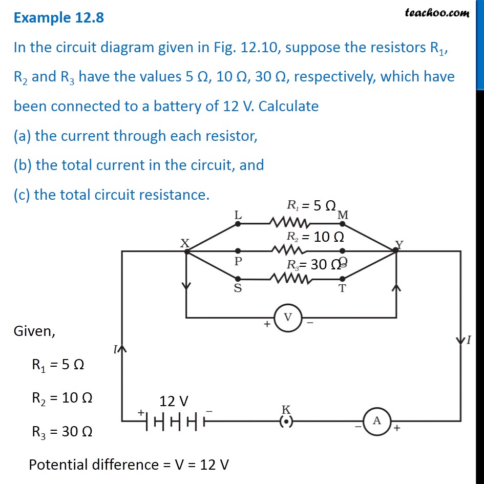
Example 12.8 - In the circuit diagram given in Fig. 12.10 ...
› thevenins-theorem-withThevenin's Theorem with solved problem - Electrically 4 U Feb 07, 2022 · Now the circuit is open-circuited. From the drawn circuit, Thevenin’s voltage is calculated between a and b. Since no current flows through 2 Ω, V TH is equal to the voltage across 3 Ω resistor. To find the voltage across the 3 Ω resistor, we need to know the current flowing through it. The total resistance in the circuit, R = 1 Ω + 3 Ω ...
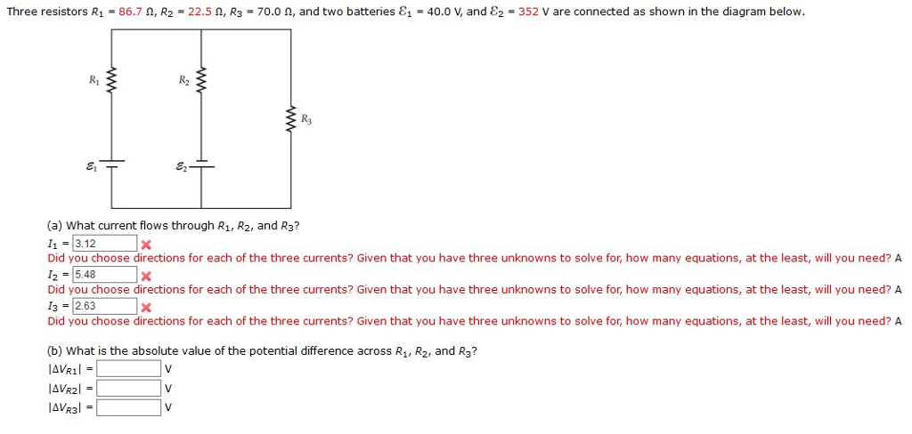
Solved Three resistors R1 = 86.7 Ω, R2 = 22.5 Ω, R3 = 70.0 ...
Parallel RLC Circuit Impedance Calculator • Electrical, RF and... The phasor diagram for a parallel RLC circuit. In the English language, a parallel RLC circuit is often called a tank circuit because it can store energy in the form of an electric field and a magnetic At zero frequency, we consider the capacitor reactance to be zero if its capacitance is infinitely large.

Circuits Flashcards | Quizlet
en.wikipedia.org › wiki › OhmOhm - Wikipedia The ohm (symbol: Ω) is the SI derived unit of electrical resistance, named after German physicist Georg Ohm.Various empirically derived standard units for electrical resistance were developed in connection with early telegraphy practice, and the British Association for the Advancement of Science proposed a unit derived from existing units of mass, length and time, and of a convenient scale ...
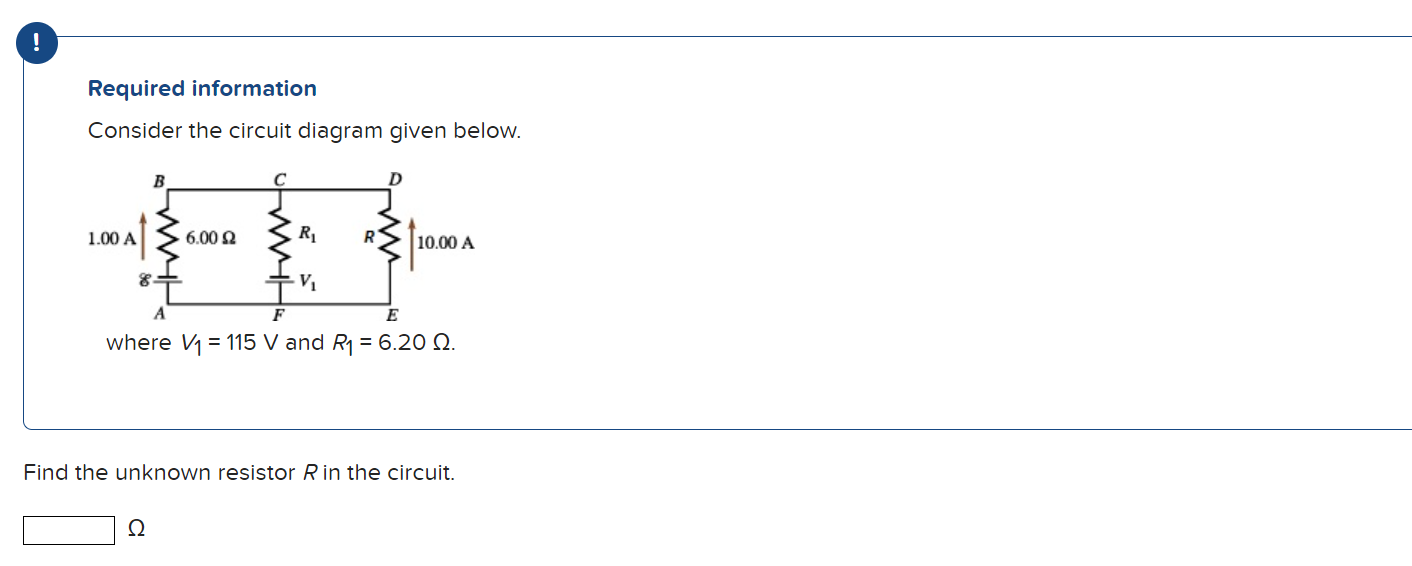
Solved ! Required information Consider the circuit diagram ...
Current Divider: What is it? Formula, Rule & Examples | Electrical4U Consider a parallel circuit of two resistors R1 and R2 connected across a supply voltage source of V volts. The circuit is connected with a 100V supply. Find out the total current and the current flowing through each resistor in the parallel circuit using the current division rule.
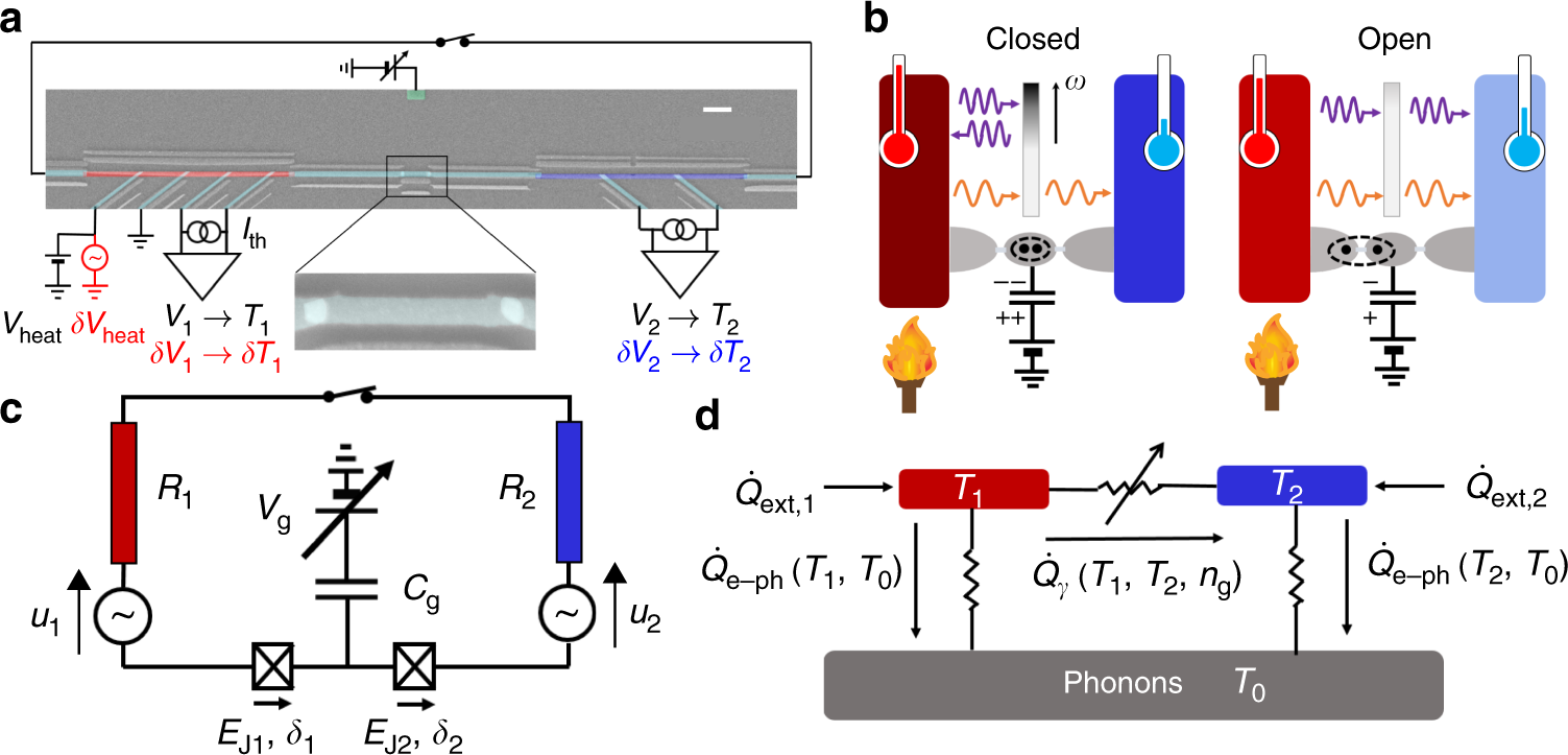
Electric field control of radiative heat transfer in a ...
Q1. The circuit diagram below shows a 6.0 V battery of negligible (6) Page 4 of 13 (b) The diagram below shows a thermistor connected in series with a resistor, R, and battery of emf 6.0 V and negligible internal resistance. Ω (2) Page 5 of 13 (c) State and explain the effect on the voltmeter reading if the internal resistance of the battery in the circuit in part (b) was not...
Resistors in Series and Parallel | Physics II
E1.1 Circuit Analysis Problem Sheet 1 The circuit is used to detect small changes in R from its nominal value of 4 kΩ. Find an expression for VAB as a function of R. If changes in VAB of 10...Whenever you use Ohm's law, you must be sure that you use the passive sign convention (with the current arrow in the opposite direction to the voltage...
Kirchhoff's Rules – University Physics Volume 2
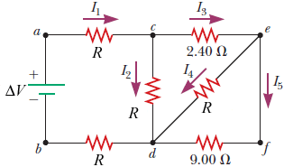
(Get Answer) - Consider the circuit in the diagram below, in which R What is the current in the R? (a) Find the equivalent resistance between terminals A and B to replace all of the resistors in the diagram, in which R = 1.55 Ω. 1.84679 Correct: Your answer is correct.

CN0540 Circuit Note | Analog Devices
Consider The Circuit In The Diagram Below In Which R 13 ω Three years at least two studies hours of debate and pages of correspondence later wording in the 2008 nec remained standing and unchanged....

Consider the circuit shown in the diagram below. For R1 = 2 ...
PDF Circuits Worksheet In which circuit below would the lamp operate correctly when switch S is closed? It would only operate in C. In A and D, closing the switch would introduce a pathway of zero resistance. ALL of the current would go down the path of no resistance leaving NO current passing through the lamp...
Solved Consider the circuit shown in the diagram below. The ...
Consider the circuit shown in the figure below. - Brainly.com We get it: you didn't come here for ads. But ads help us give you free access to Brainly. Please consider whitelisting us!

Consider the circuit shown in the diagram. Find the current ...
PDF Recitation 6 13 looks like a Kirchho's loop rule involving only branches 1 and 2. The rst term −(220Ω)I1 looks like a V = IR resistor drop in the direction of the current on branch 1, so let's add a 220Ω resistor to branch 1. Because the voltage drops in our loop...21 and 23 is pretty straightforward. Consider the circuit.

Problem 2 Consider the circuit shown in the diagram below ...
Chapter 11 Circuits

In the figure below, R = 16.0 \Omega and the battery emf is ...
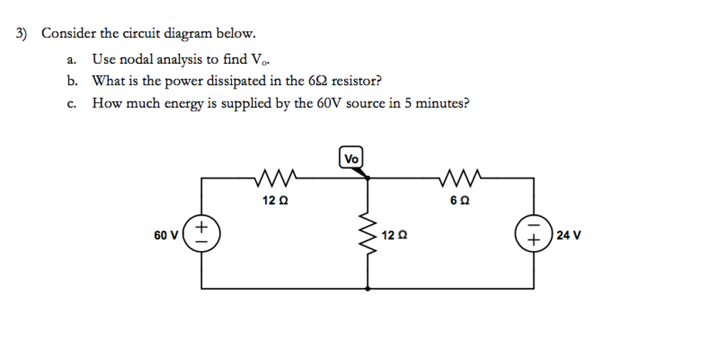
Solved Consider the circuit diagram below. a. Use nodal ...
SOLVED:Consider the circuit shown in the diagram below. The ...

The resistor R in the figure below dissipates 13 W of power ...
Kirchhoff's Rules – University Physics Volume 2

Consider the circuit in the diagram below. in which r = 11 ω.
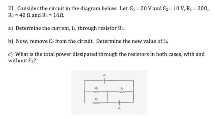
Solved III. Consider the circuit in the diagram below. Let ...
Kirchhoff's Rules – University Physics Volume 2

Consider the circuit shown in the figure below. (Let R = 18.0 ...

Problem 2 Consider the circuit shown in the diagram below ...
AP Physics C: Electricity and Magnetism Samples and ...
Solved Consider the circuit shown in the figure below. (Let ...
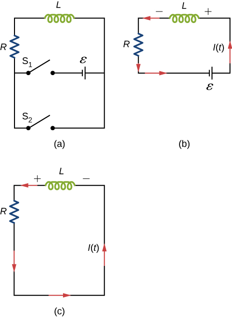
RL Circuits – University Physics Volume 2
0 Response to "36 consider the circuit in the diagram below, in which r = 13 ω."
Post a Comment