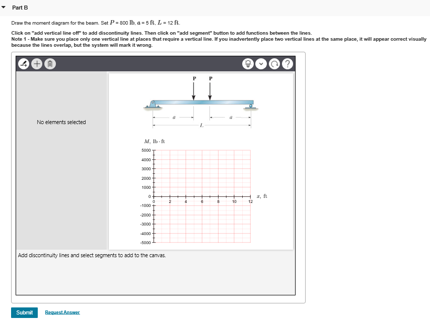
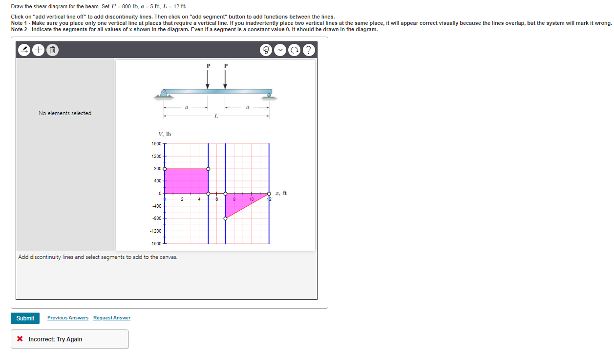
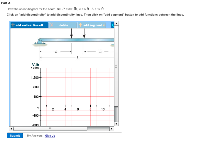
36 Draw The Shear Diagram For The Beam. Set P = 800 Lb, A = 5 Ft, L = 12 Ft.
[Solved] Draw the shear and moment diagrams for the beam ... Draw the shear and moment diagrams for the beam in terms of the parameters shown. Given: P = 800 lb a = 5 ft L = 12 ft. Draw the shear and moment diagrams for the beam. Units Used: kN. Draw the shear and moment diagrams for the beam. Units Used: kN = 103 N Given: a = 2 m b = 4 m = w 1.5kN/m. Draw the shear and moment diagrams for the beam ... - Holooly Draw the shear and moment diagrams for the beam in terms of the parameters shown. Given: P = 800 Ibquad a = 5 ftquad L = 12 ft | Holooly.com.
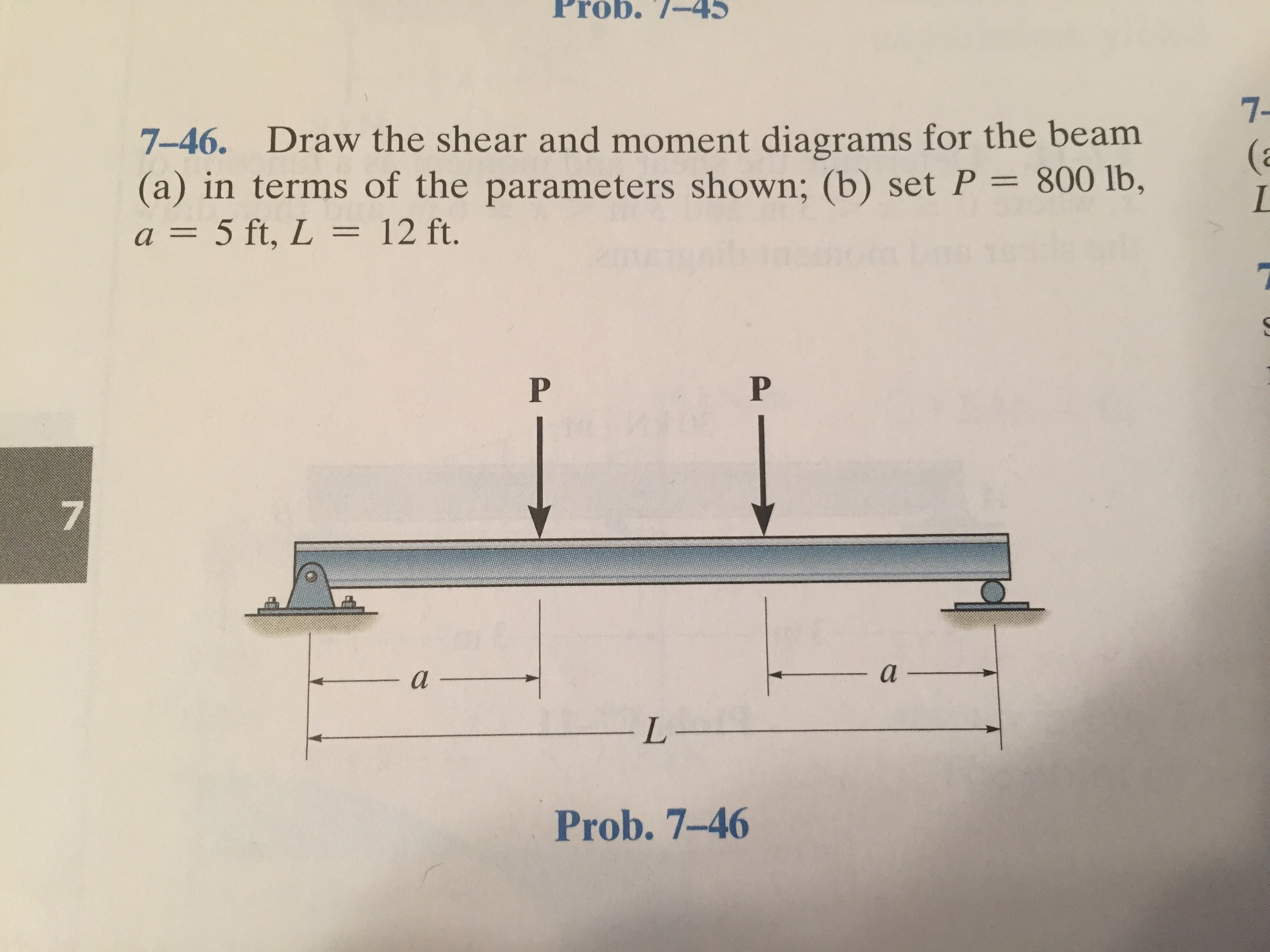
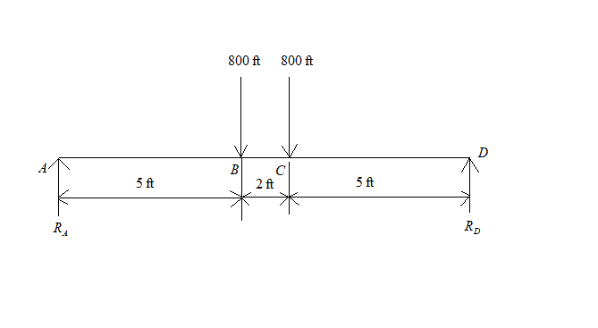
PDF Exercises Corresponding to Section 7 and moment at points D and E in the overhang beam. Point D is located just to the left of the roller support at B, where the couple moment acts. Exercises Corresponding to Section 7.2 7-46 Draw the shear and moment diagrams for the beam (a) in terms of the parameters shown; (b) set P = 800 lb, a = 5 ft, L = 12 ft.
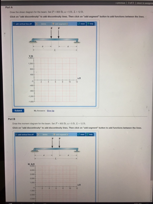
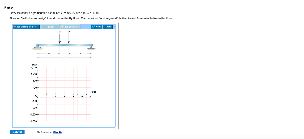
Draw the shear diagram for the beam. set p = 800 lb, a = 5 ft, l = 12 ft.
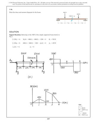
PDF Example 6 - Etu Draw the shear and moment diagrams for the beam shown in Fig. 6-7a. (a) L w 0 w —— 2 0 L (b) 2- L 3 w —— 2 0 L — 3 w 0 L2 w 0 Solution Support Reactions.The distributed load is replaced by its resultant force and the reactions have been determined as shown in Fig. 6-7b. Shear and Moment Functions.A free-body diagram of a beam ... PDF Chapter 4 Shear and Moment In Beams - ncyu.edu.tw section of a beam : draw a free-body diagram that expose these ... w/x = 360/12, or w = 30x lb/ft. Part 2 The location of the section where the shear ... 5(8.165)3 = 5443 lb· ft =1000 −15x2 =0 dx dM. 4.4 Area Method for Drawing Shear- Moment Diagrams Useful relationships between the loading, shear force, and bending moment can be derived ... Shear Force and bending moment diagram - ExtruDesign Steps to draw Shear force and Bending moment diagrams. In SFD and BMD diagrams Shear force or Bending moment represents the ordinates, and the Length of the beam represents the abscissa. Consider the left or the right portion of the section. Add the forces (including reactions) normal to the beam on the one of the portion.
Draw the shear diagram for the beam. set p = 800 lb, a = 5 ft, l = 12 ft.. PDF Hibbeler Chapter 6 Part 1 (463-486) - Auburn University Draw the shear and moment diagrams for the double overhanging beam. 3 ft 3 ft 200 lb/ft 400 lb 6 ft 400 lb A B M (lb ft) x (ft) V (lb) 0 400 0 12 x (ft) 600 1200 1200 300 600 400 3 6 369 12 9 Ans: Hibbeler_Chapter 6_Part 1 (487-517).qxd 2/12/13 11:07 AM Page 499 (PDF) Mechanics of materials solution manual - Academia.edu mechanics of materials solution manual. Chapter# 6-14. Enter the email address you signed up with and we'll email you a reset link. Answered: 4. Draw the shear and moment diagrams… | bartleby Browse 5+ million homework and textbook solutions, concept explainers, videos and more. Search concepts or drop in your homework problem! Our library grows every minute-keep searching! Engineering Civil Engineering Q&A Library 4. Draw the shear and moment diagrams for the beam. 400 lb/ft 600 lb-ft 15 ft. 4. Solved Draw the shear diagram for the beam. Set P = 800 lb ... Draw the shear diagram for the beam. Set P = 800 lb, a = 5 ft. L = 12 ft. Click on "add discontinuity" to add discontinuity lines. Then click on "add segment" button to add functions between the lines. Draw the moment diagram for the beam. Set P = 800 lb, a = 5 ft, L = 12 ft. Click on "add discontinuity" to add discontinuity lines. Then click on "add
(PDF) Chapter 7 1 solution | shasti darran - Academia.edu P P *7-40. Draw the shear and moment diagrams for the beam (a) in terms of the parameters shown; (b) set P = 800 lb, a = 5 ft, L = 12 ft. a a L 582 f7 Solutions 44918 1/27/09 10:39 AM Page 583 © 2010 Pearson Education, Inc., Upper Saddle River, NJ. All rights reserved. SOLVED:'5) Draw a shear and moment diagram for the ... Draw the shear and moment diagrams for the beam (a) in terms of the parameters shown; (b) set $P=800 \mathrm{lb}$ $a=5 \mathrm{ft}, L=12 \mathrm{ft}$. Engineering Mechanics: Statics and Dynamics 14th (physics) Draw the shear force and bending moment diagrams for beam ... Draw the shear-force and bending-moment diagrams for this beam. Solution 4.5-12 Beam with distributed loads SECTION 4.5 Shear-Force and Bending-Moment Diagrams 275 0.8 m 3000 N/m A B 0.8 m 1.6 m 0.8 m 3000 N/m A V M B 0.8 m 1.6 m 1500 N/m 1200 -1200 960 480 480 (N) (N. m) 0 0 Problem 4.5-13 A cantilever beam AB supports a couple and a ... Hibeler SM Chapter 7, 8, 9, 10 y 11.pdf - Academia.edu 545 • 7-1. Determine the internal normal force and shear force, and the bending moment in the beam at points C and D. Assume the support at B is a roller. Point C is located just to the right of the 8-kip load.
PDF HW 19 SOLUTIONS - University of Utah 6—25. Draw the shear and moment diagrams for the beam- The two segments are joined together at B. 8 kip 3 kip,ft 5 ft *6—20. Draw the shear and moment diagrams for the beam, and determine the shear and moment throughout the beam 10 kip 2 kip/ft g Kip 8 kip 40 kip.ft as functions of x. Support Reactions: As shown on FBD. Shear and Moment ... SOLVED:Draw the shear and moment diagrams for the beam (a ... Draw the shear and moment diagrams for the beam (a) in terms of the parameters shown; (b) set $P=800 \mathrm{lb}$ $a=5 \mathrm{ft}, L=12 \mathrm{ft}$. Chapter 7 P P *7-40. Draw the shear and moment diagrams for the beam (a) in terms of the parameters shown; (b) set P = 800 lb, a = 5 ft, L = 12 ft. a a L 582 7 Solutions 44918 1/27/09 10:39 AM Page 583 © 2010 Pearson Education, Inc., Upper Saddle River, NJ. All rights reserved. This material is protected under all copyright laws as they currently exist. Draw the shear and bending-moment diagrams for the beam ... Set P=800 lb, a=5 ft, L=12 ft. Method of Area for Constructing the Moment Diagram of a Beam: Method of area is very useful when you have simple forces acting on a beam (e.g. force at a certain ...
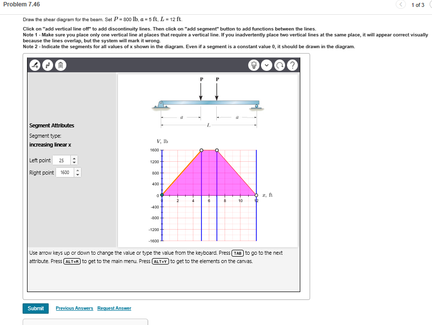
Solved Problem 7.46 1 of 3 Draw the shear diagram for the ...
[Solved] Draw the shear and moment diagrams for the beam ... Draw the shear and moment diagrams for the beam in terms of the parameters shown. Given: P = 800 lb. a = 5 ft. L = 12 ft.
Solved Draw the shear diagram for the beam. Set P = 800 lb ...
PDF Beam Design Formulas With Shear and Moment Shear and moment diagrams and formulas are excerpted from the Western Woods Use Book, 4th edition, and are provided herein as a courtesy of Western Wood Products Association. Introduction Notations Relative to "Shear and Moment Diagrams" E = modulus of elasticity, psi I = moment of inertia, in.4 L = span length of the bending member, ft.
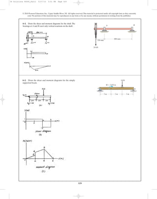
329 6–1. Draw the shear and moment diagrams for the shaft ...
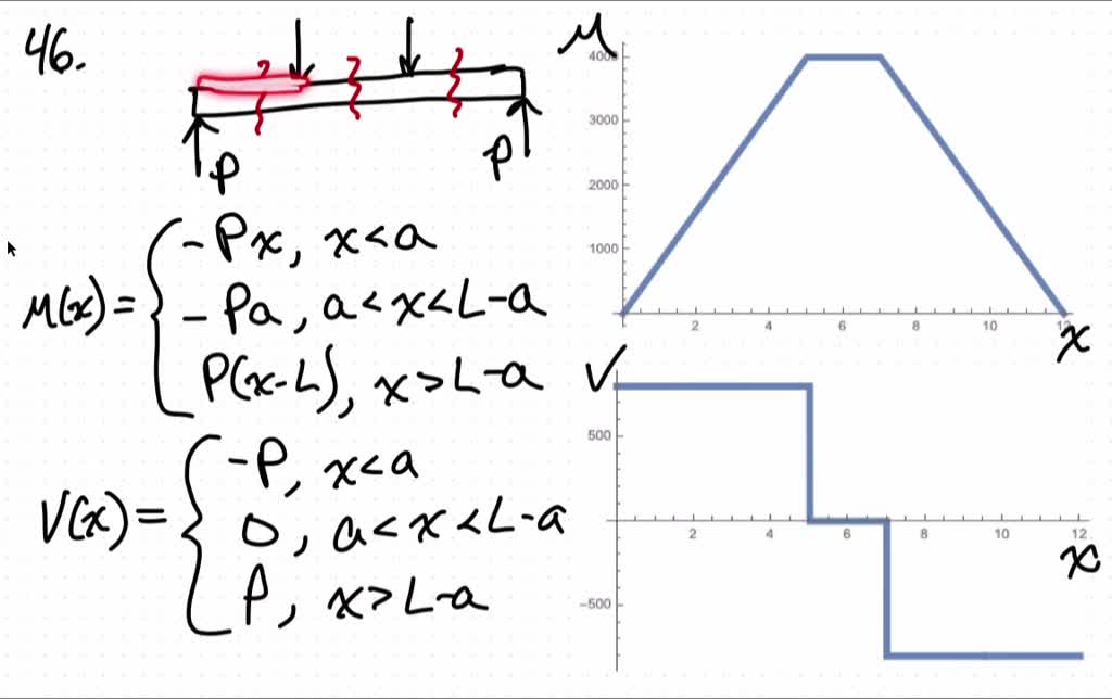
MODUEL 7-2 SCD.pdf - 7-46 Draw the shear and moment ... 7-46 Draw the shear and moment diagrams for the beam A) in terms of the parameters shown B) Set P = 800lb, a = 5 ft and L = 12 ft. it p EE P p p tr b f l m t l l t plfa li.ro a1Tp O O X p A OExca TEE 0 P EM O M P acxLL a t y OV OEM O pxt.PK a tM O M Pa L al x EL Fy _O V P M O M PCL x o M P L x B f 800lb a Sft 4 12ft For OEXLSftEFy OV P 8001bM px 800xlb.tt For SftExE7ft EFy 0 V O 800 1 8006 5 tM 0 800 1 800 4000 tM O Ox 40004M
Solved Problem 7.46 1 of 3 Draw the shear diagram for the ...
Solved Draw the shear diagram for the beam. Set P-800 lb ... Set P-800 lb, a-5 ft, L = 12 ft Click on "add discontinuity" to add discontinuity lines. Then click on "add segment" button to add functions between the lines add vertical line off delete add segment ? help reset. Question: Draw the shear diagram for the beam. Set P-800 lb, a-5 ft, L = 12 ft Click on "add discontinuity" to add discontinuity lines. Then click on "add segment" button to add functions between the lines add vertical line off delete add segment ? help reset.
Answered: Draw the moment diagrams for the beam… | bartleby
PDF CHAPTER 2 Shear Force And Bending Moment 5 kN/m 12 kN/m 50 kNm 40 kN 1.5 2 A B CLASS EXERCISE ... If P = 20 kN and L = 6 m, draw the SFD and BMD for the beam. P kN L/2 L/2 A B EXAMPLE 4 . ... figure, then draw the shear force diagram (SFD) and bending moment diagram (BMD). 5 kN/m 3 m A B EXAMPLE 6 . By taking the moment at A:

Shear and Moment Diagrams Example
[Solved] Draw the shear and moment diagrams for the beam ... Draw the shear and moment diagrams for the beam in terms of the parameters shown. Given: P = 800 lb a = 5 ft L = 12 ft A client decides not to record an auditor's proposed adjustments that collectively
Solved Draw the shear diagram for the beam. Set P = 800 lb ...
x z y C 15 ft 2 ft F 1 F 2 3 ft Probs 74344 739 The ... Draw the shear and moment diagrams for the beam (a) in terms of the parameters shown; (b) set P = 600 lb, a = 5 ft, b = 7 ft. A B P a b Prob. 7-46 7-47. Draw the shear and moment diagrams for the beam (a) in terms of the parameters shown; (b) set P = 800 lb, a = 5 ft, L = 12 ft.

Statics 7.45 - Draw the shear and moment diagrams for the shaft in terms of the parameters shown.
h 19.pdf - Beams are structural members designed to ... View h 19.pdf from PHYSICS AN 2025 at Zhejiang Normal University. Beams are structural members designed to support loadings applied perpendicular to their axes. In general, they are long and straight
SOLUTION
Chapter 7, Internal Forces Video Solutions ... - Numerade Show that the deflection curve of the cable discussed in Example 7.13 reduces to Eq. 4 in Example 7.12 when the hyperbolic cosine function is expanded in terms of a series and only the first two terms are retained.
Solved Draw the shear and moment diagrams for the beam in ...
Shear Force and bending moment diagram - ExtruDesign Steps to draw Shear force and Bending moment diagrams. In SFD and BMD diagrams Shear force or Bending moment represents the ordinates, and the Length of the beam represents the abscissa. Consider the left or the right portion of the section. Add the forces (including reactions) normal to the beam on the one of the portion.

Drawing Shear and Moment Diagrams for Beam
PDF Chapter 4 Shear and Moment In Beams - ncyu.edu.tw section of a beam : draw a free-body diagram that expose these ... w/x = 360/12, or w = 30x lb/ft. Part 2 The location of the section where the shear ... 5(8.165)3 = 5443 lb· ft =1000 −15x2 =0 dx dM. 4.4 Area Method for Drawing Shear- Moment Diagrams Useful relationships between the loading, shear force, and bending moment can be derived ...
Exercises Corresponding to Section 7.1 7–18 Determine the ...
PDF Example 6 - Etu Draw the shear and moment diagrams for the beam shown in Fig. 6-7a. (a) L w 0 w —— 2 0 L (b) 2- L 3 w —— 2 0 L — 3 w 0 L2 w 0 Solution Support Reactions.The distributed load is replaced by its resultant force and the reactions have been determined as shown in Fig. 6-7b. Shear and Moment Functions.A free-body diagram of a beam ...
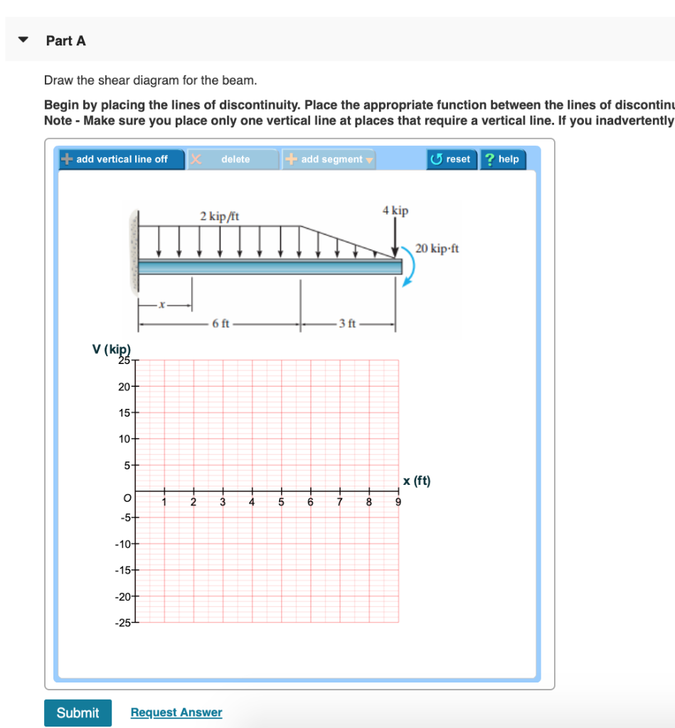
Solved Problem 6.8 17 of 51> Review 2 kip/It 4 kip 20 kip-ft ...
Problem 9.1 Two beam segments, AC and CD, are connected ...
draw the shear and moment diagrams for the beam a in terms of the parameters shown b set p800 mathrm
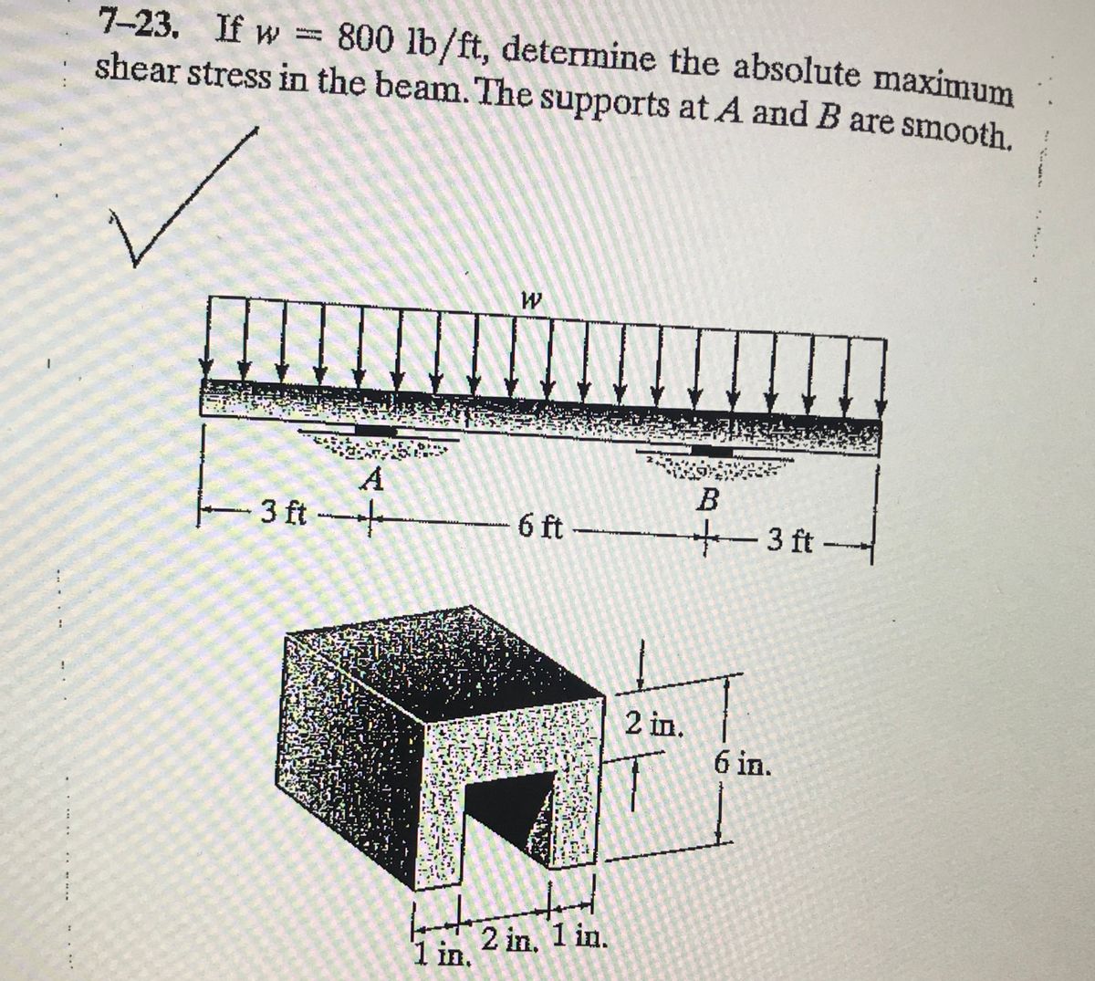
Answered: 7-23. If w =800 lb/ft, determine the… | bartleby

Draw the shear and bending moment diagrams for the beam (a ...
Shear Forces and Bending Moments
Ch06 07 pure bending & transverse shear
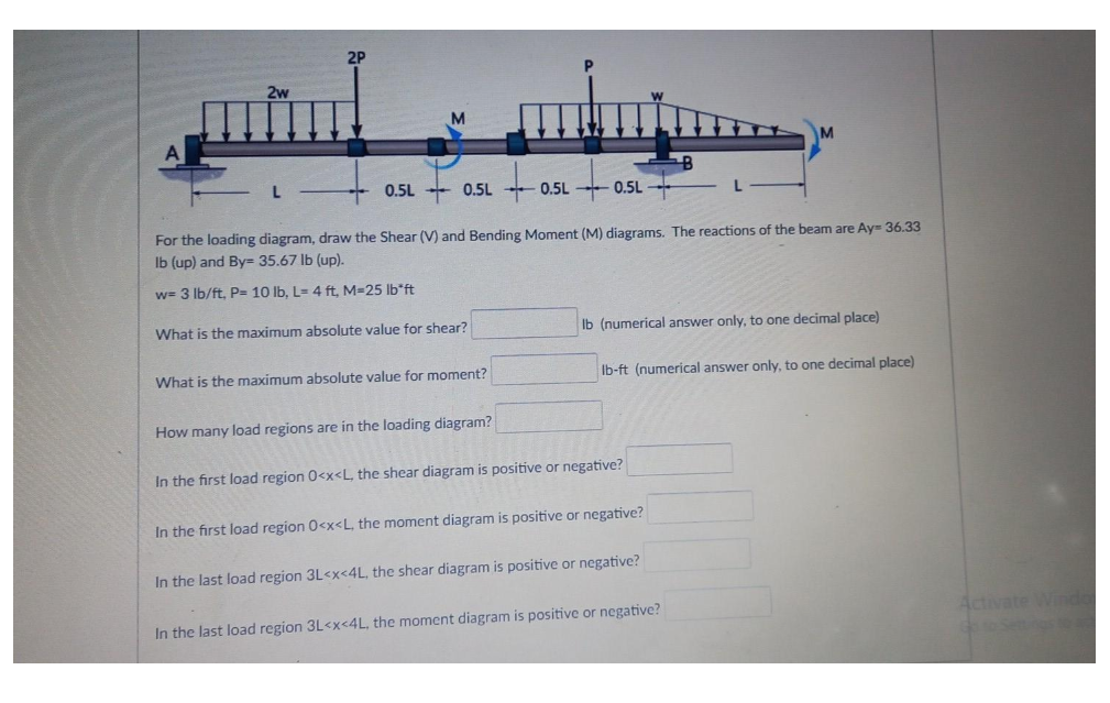
Answered: 2P 2w M A L - 0.5L + 0.5L 0.5L 0.5L L-… | bartleby
![Solved 5. [7-46] Draw the shear and moment diagrams for the ...](https://d2vlcm61l7u1fs.cloudfront.net/media%2Fcb1%2Fcb181ecc-92fa-4650-af18-4b3859cffef4%2Fphp3Gr26R.png)
Solved 5. [7-46] Draw the shear and moment diagrams for the ...
Untitled
Exercises Corresponding to Section 7.1 7–18 Determine the ...
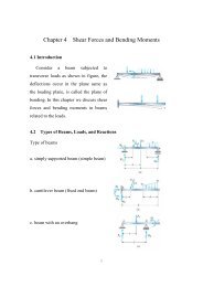
Chapter 7
329 6–1. Draw the shear and moment diagrams for the shaft ...
PROBLEM 5.1
SOLUTION
Answered: Draw the shear diagram for the beam.… | bartleby
Chapter 7, Internal Forces Video Solutions, Engineering ...
Solved Part A Draw the shear diagram for the beam. Set P 800 ...
Solved Part A Draw the shear diagram for the beam. Set P 800 ...

Draw the shear and bending-moment diagrams for the beam. Set ...
PROBLEM 5.1
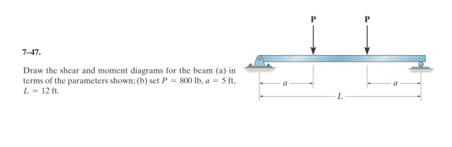
Solved 7-47 Draw the shear and moment diagrams for the beam ...
Answered: The shear-force diagram for a beam is… | bartleby
SOLUTION
0 Response to "36 Draw The Shear Diagram For The Beam. Set P = 800 Lb, A = 5 Ft, L = 12 Ft."
Post a Comment