37 ring and barrier diagram
In the ring-barrier designer, modify the structure so you have phase 10 and phase 11 within their own barriers. Then you can type in the phase numbers in the ped phase column. Till now you should already have a beautiful ring-barrier diagram. The ring and barrier diagram for concurrent pedestrian signal timing is shown in Figure 2-4. The pedestrian phases 2P, 4P, 6P and 8P time concurrently Figure 2-6 shows the ring diagram for EPP. While this phasing eliminates conflicts for pedestrians during EPP, it increases both vehicular and...
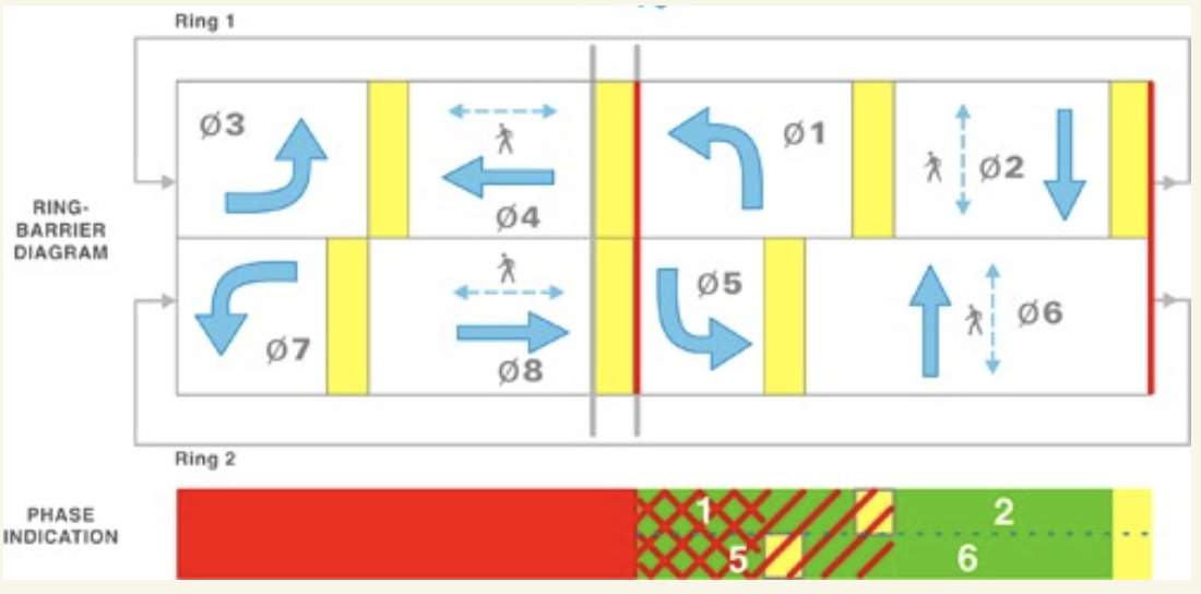
Ring Barrier Diagram. A graphical representation of phases within a set of rings and phases within a set of barriers. Saturation Flow Rate. A phase diagram illustrating the phase plan, cycle length, green time, change interval, and clearance time interval of a signalized intersection.
Ring and barrier diagram
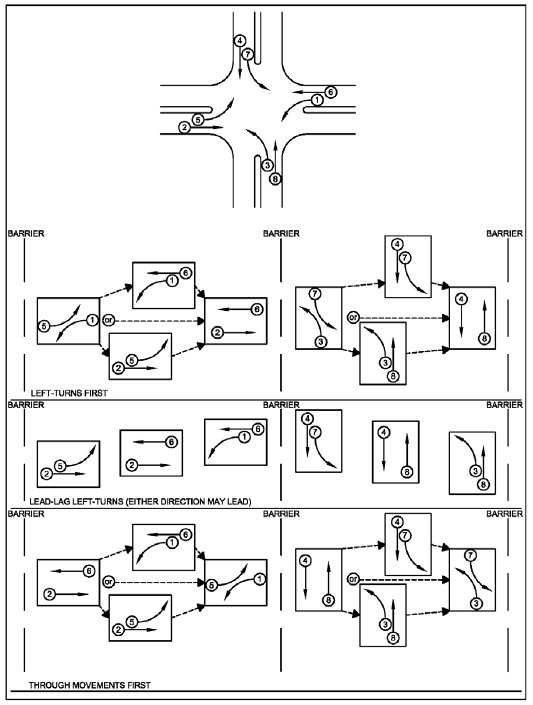
Traffic engineers use a ring-and-barrier diagram to sketch out how different phases of the signal are allowed to operate. Here's a ring-and-barrier diagram for our example intersection. The first phase is the major street left turns, then the major street vehicle and pedestrian through movements... 2 Barrier diagrams. 3 Transocean 3 3.1 Facts 3.2 Event sequence 3.3 Design problems 3.4 Organizational problems 3.5 Judgemental errors 3.6 Barriers which Structural failure, wedge rings Structural failure, bracing and column lost Ballast system, portlight Gas blow-out Gas blow-out Ballast... Compared with the ring-barrier framework used for ring structures (or phasing plans) in signalized control of intersections in the United States, the Dutch framework has no explicit barriers, but only a requirement to respect pairwise conflicts. This paper describes how ring structures can be modeled...
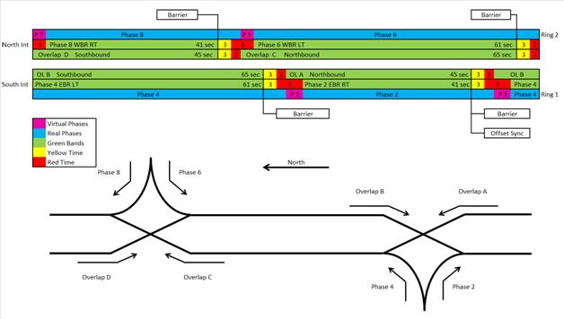
Ring and barrier diagram. In the ring-barrier designer, modify the structure so you have phase 10 and phase 11 within their own barriers. Then you can type in the phase numbers in the ped phase column. Till now you should already have a beautiful ring-barrier diagram. Have a cup of coffee to celebrate.. 2. Input all the... Figure 5.5 Intersection layout and Ring-and-Barrier Diagram at Int. TH13 & Portland Ave. ..... 46 Figure 5.6 Estimated green time VS observed green time depending on The numbers on the green bars in the ring-and-barrier diagram show the max green time, plus yellow and red clearance time. 2. Ring and Barrier Diagram for Montrose Pkwy & E Jefferson St denoting the phase sequence. Each column of phases is active simultaneously. Let λ1, λ2, . . . , λr and ψ1, ψ2, . . . , ψr denote a collection of DMD eigenvalues and DMD modes obtained from the trafc ow data as described above. Prepare a ring barrier diagram that represents this phasing showing each phase and the movement or movements that it controls, the sequence of the phases in each of the two rings, and the locations of the barriers that divide the two concurrency groups.
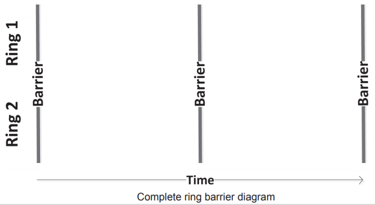
Vehicle trajectories are shown as dots on the time-space diagrams for each main approach. The dot color indicates the vehicle speed, as defined on the color map to the right of each diagram. The ring barrier diagram for each of the two sites is shown in Figure 24. Ring-and-Barrier Diagrams (cont.) An Example for a 4-Leg Intersection. Systems of Traffic Signals (cont.) An Example Time-Space Diagram for Coordinated Signals. The ring barrier may consist of a natural wall, ring gates, or ropes. • Indoor Rings. Floors surfaces that do not provide safe footing for dog and handler must be covered by mats or suitable regulations described below. Jump construction and diagrams will be found in the back of this rulebook. • Also, Locate The Pedestrian Cross In This Diagram And Determine The Traffic Signal Cycle Length. As per the NEMA phase ing conventions followed, the standard ring-barrier diagram along with pedestrian cross.
dot-barrier confinement (black) and (class-XIII) barrier-ring confinement (light gray). Class-III (yellow) defines a forbidden energy gap region with no The energy phase diagrams yield a glimpse of the character modulation of the electronic state. By focusing on solutions listed in Table 2, it is possible to... Figure 4-9 Ring-and-barrier diagram showing split phasing. Figure 4-10 Prohibited left turns by time of day. Figure 4-11 Guidelines for determining the Figure 4-14 Ring-barrier diagrams showing a leading pedestrian interval and an exclusive pedestrian phase4-19. Figure 4-15 Phase diagram... Figure 5.6 Signal Ring and Barrier Diagrams for Normal Weather Plan, Slushy Safe Plan, Snowy Safe Plan, Slushy Optimal Plan, and Snowy Optimal Plan for The diagram illustrates the relationship among intersection spacing, signal timing, and vehicle movement. As for optimizing and modifying... Ring-and-barrier diagrams A way to line up phases. Phases within a barrier are compatible. zinglonhgauowedlwpedetwanmgzkig.lt Anag ( 有权 先 Time-space diagram w/ ring-and-barriers Northbound traffic affected by bottom bar. Southbound traffic affected by top bar. igoingtoward.co ) N...
CHAPTER XX
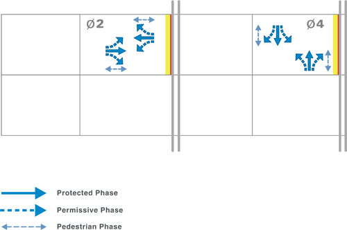
Additionally, Exhibit 3-2 shows a standard ring and barrier diagram. The ring shows phases that may operate sequentially and are typically conflicting. The barrier typically separates east-west movements from north-south.
Signal Phasing | SpringerLink
Wiring practice by region or country. North American practice. United Kingdom practice. Regulation of electrical installations. BS 7671 UK wiring regulations. IEC 60364 IEC international standard.
Chapter 4 - Signalized Intersections: Informational Guide ...
Dual Ring Control. Single Ring (Sequential Phases). Multi-Rings and Barriers. Phasing Parameters. Advanced Traffic Management Systems (ATMS). Time-Space Diagrams. Control Philosophies for Computerized Traffic Signal Systems.

Dual-ring eight-phase control defined by NEMA nomenclature ...
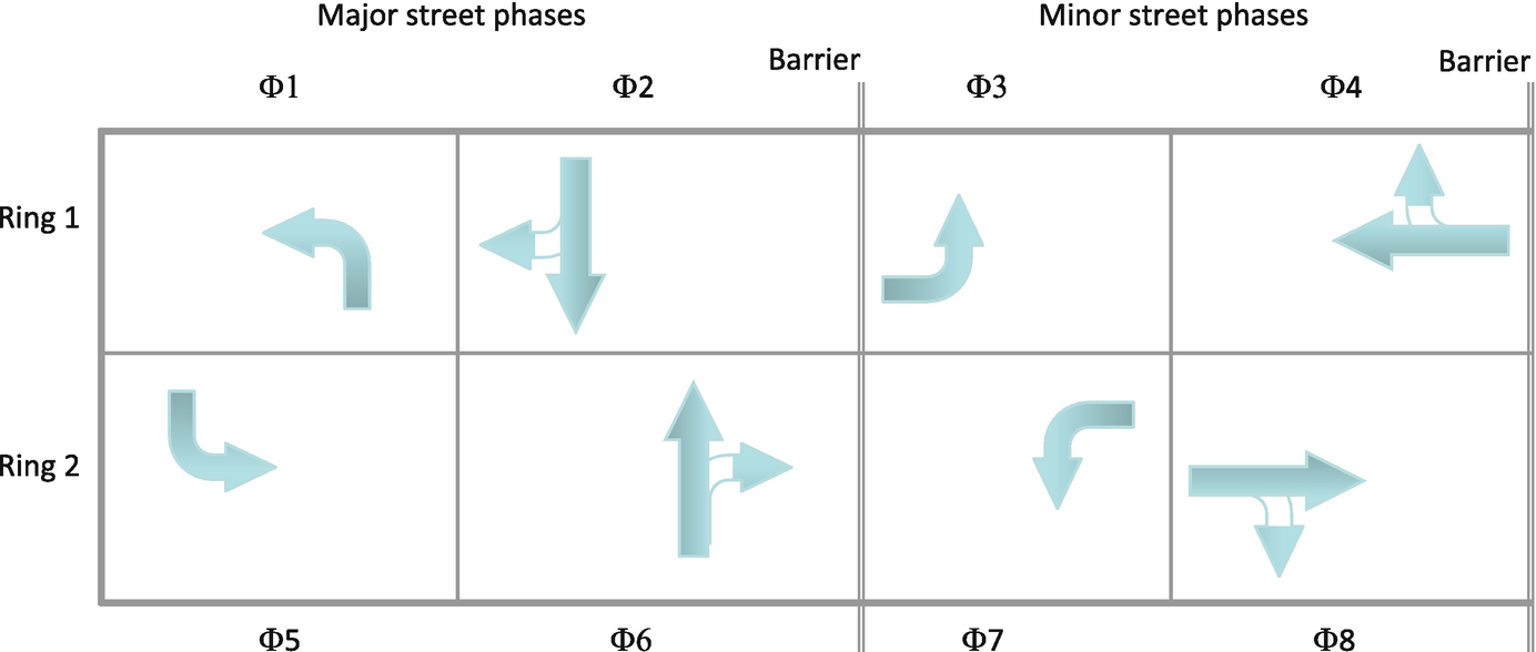
Barriers: In dual ring operation, a barrier is the point at which the phases in both rings must end simultaneously. Barriers typically separate major and minor street phases. Figure 7.4 provides an example of a standard NEMA eight-phase, dual ring-and-barrier diagram, with protected leading...

Traffic Engineering 1. Draw a Ring-and-Barrier Diagram ...
Ring-barrier diagram showing a right turn overlap phasing, which assigns a protected right-turn phase to the complementary left turn movement on the intersecting roadway. 600. If only the average speed is known, the percentile speeds are calculated as shown.
CHAPTER 7 TRAFFIC SIGNAL DESIGN – OPERATIONS AND COORDINATION
In this ring and barrier diagram, which phases cannot be reversed in their sequencing? In this ring and barrier diagram, what sequencing is used for the protected left turns?
StealthNet Installation – Bird Barrier
The VISSIM Ring Barrier Controller (RBC) emulator has been integrated into VISSIM. Lock Diagram This option allows you to lock the diagram such that clicking within the Timing Diagram will no longer change the timing.
3 Whose Turn is it? Phasing, Rings, and Barriers
When reading a ring and barrier diagram, vehicular movements drawn with solid lines do not have any conflicting movements associated with them.

Traffic Engineering 1. Draw a Ring-and-Barrier Diagram ...
Download scientific diagram | Ring-and-barrier diagram and TSP strategies. from publication: Transit signal priority optimization for urban traffic network ... signal phasing allocation. Figure 5 shows a sam- ple four-phase ring diagram with TSP strategy of green extension. Phase 1 includes a through...
14 What Do You Know About Phasing and Ring Barrier Diagrams?
In this diagram, a ring is a sequence of phases that are incompatible and thus must be served in a particular order, and a barrier is a 2, the phases in both rings must be simultaneously turned to red at the barrier. Various phase combinations and orders can be used to define a signal phase...

Modeling Traffic Operations in Synchro/SimTraffic – Part II ...
Exhibit 5-5 Ring-and- Barrier Diagram Showing Permied LeÂ-Turn Phasing Signal Timing Manual, Second Edion. Chapter 5. Introducon to Timing Plans 5-7 • Challenges: The added left-turn phase increases the lost time within the cycle length and may increase delay for other movements.
3 Whose Turn is it? Phasing, Rings, and Barriers
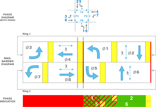
The ring barrier diagram species the safe sequencing of phases (and thus the movements that they control) at a signalized intersection. A complete ring barrier diagram for the phases that control the east-west and north-south movements is shown in Figure 59.

Ring-Barrier Diagram with a Leading Pedestrian Interval ...
Compared with the ring-barrier framework used for ring structures (or phasing plans) in signalized control of intersections in the United States, the Dutch framework has no explicit barriers, but only a requirement to respect pairwise conflicts. This paper describes how ring structures can be modeled...
Traffic Signal Timing Manual: Chapter 6 - Office of Operations
2 Barrier diagrams. 3 Transocean 3 3.1 Facts 3.2 Event sequence 3.3 Design problems 3.4 Organizational problems 3.5 Judgemental errors 3.6 Barriers which Structural failure, wedge rings Structural failure, bracing and column lost Ballast system, portlight Gas blow-out Gas blow-out Ballast...
3 Whose Turn is it? Phasing, Rings, and Barriers
Traffic engineers use a ring-and-barrier diagram to sketch out how different phases of the signal are allowed to operate. Here's a ring-and-barrier diagram for our example intersection. The first phase is the major street left turns, then the major street vehicle and pedestrian through movements...

Protected–permissive left turn phasing with flashing yellow ...

Typical example of a signal phase sequence (NEMA ring-and ...

Ring barrier controller structure with stage definition for a ...
Analysis of Two Signals - Problem 3 Assume the | Chegg.com
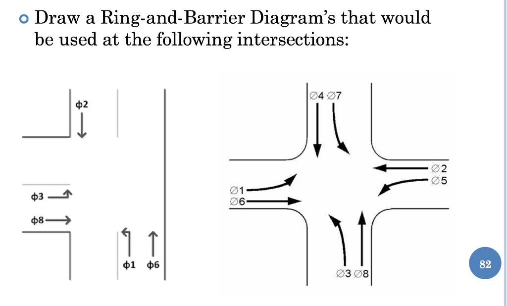
Solved o Draw a Ring-and-Barrier Diagram's that would be ...
![PDF] Barrier crossing of a semiflexible ring polymer ...](https://d3i71xaburhd42.cloudfront.net/89559afeb23044c3bca9549385617313a6b31508/6-Figure1-1.png)
PDF] Barrier crossing of a semiflexible ring polymer ...
Solved Please complete the ring and barrier diagram for the ...

Chapter 5 - Introduction to Timing Plans | Signal Timing ...
The Berry phase as a function of the barrier height g for one ...

Bi-directional integral pumping devices for dual mechanical ...
CHAPTER 7 TRAFFIC SIGNAL DESIGN – OPERATIONS AND COORDINATION
3 Whose Turn is it? Phasing, Rings, and Barriers
CHAPTER XX
3 Whose Turn is it? Phasing, Rings, and Barriers
Traffic Control Systems Handbook: Chapter 7 Local Controllers ...
Traffic Signal Timing Manual: Chapter 4 - Office of Operations
FHWA Office of Operations - Appendix F: Actuated Signal Control
234.6 Diverging Diamond Interchanges - Engineering_Policy_Guide
CHAPTER XX
3 Whose Turn is it? Phasing, Rings, and Barriers

Ring-barrier diagram showing typical cycle (top) and queue ...
3 Whose Turn is it? Phasing, Rings, and Barriers
0 Response to "37 ring and barrier diagram"
Post a Comment