40 log splitter detent valve diagram
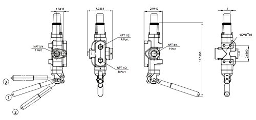
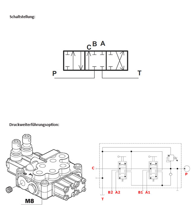
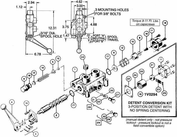
Directional control valve - Log splitter Pressure release detent kit Pressure relief valve Lever system Valve body Spool ESpool control 4/7 Code Part No. Description A 414.00.00.04 Valve body B 414.01.00.08 Spool C 414.04.00.00 Pressure release detent kit D Pressure relief valve E Spool control F Lever system Sep 2013 How to Troubleshoot a Log Splitter Detent Valve | Synonym Sep 29, 2017 · 1 Find the diagram. Find the diagram of the detent valve set up. There will be input valves for the pressurized and un-pressurized hose connections, and the diagram will show you which ones go on which side of the detent valve and in what order. If the hydraulic hoses are hooked up incorrectly, then the valve won't be able to function properly.
Speeco Log Splitter Parts Diagram - Wallpaperidle Nov 18, 2021 · Log splitter detent valve diagram. Part # 29 in the diagram. Split fire, speeco commercial kinetic log splitter parts diagram, ariens 917002 019000 34 ton log splitter parts diagrams, log splitter parts gumtree australia free local classifieds, parts amp service split fire, oregon scientific s402028h0 owner s manual pdf download, supersplit ...

Log splitter detent valve diagram
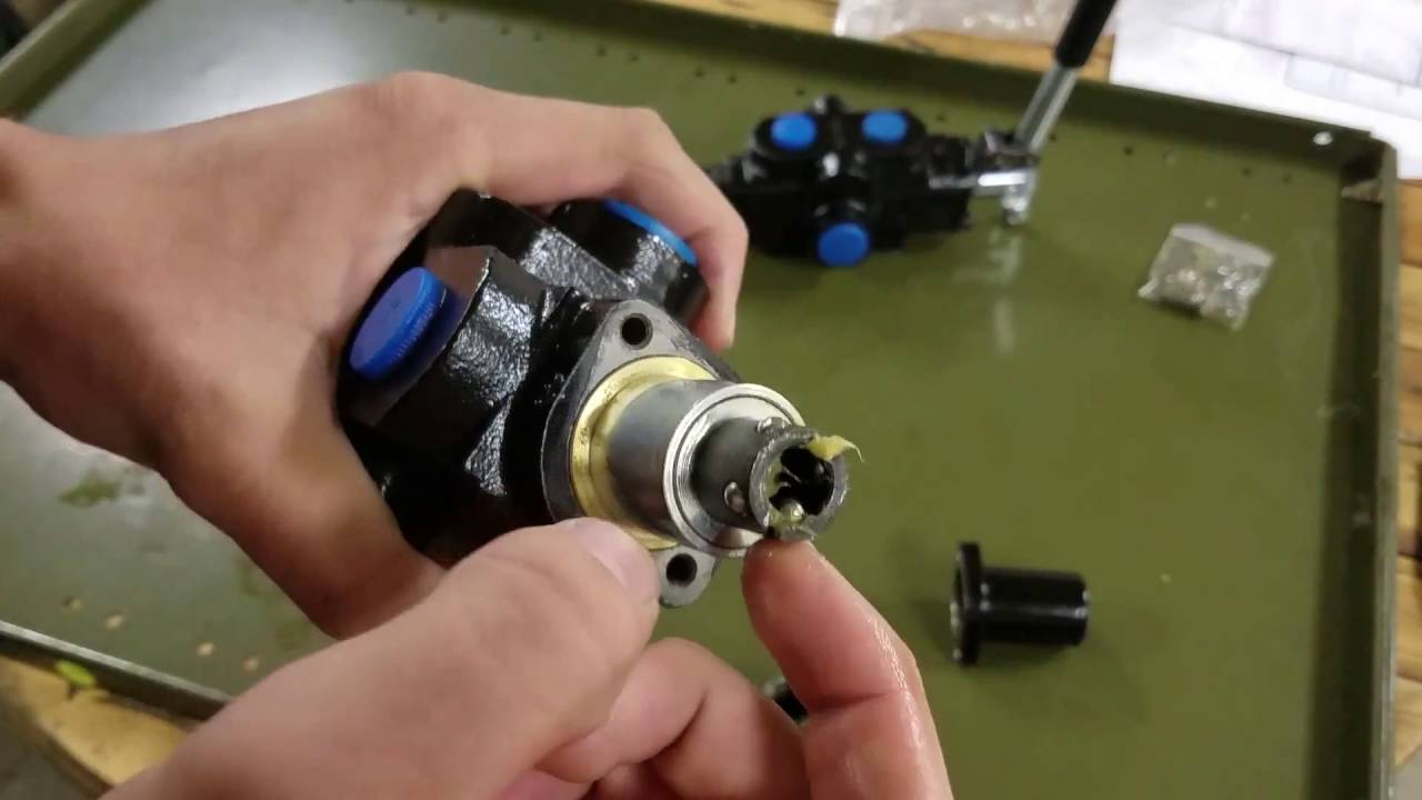
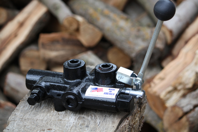
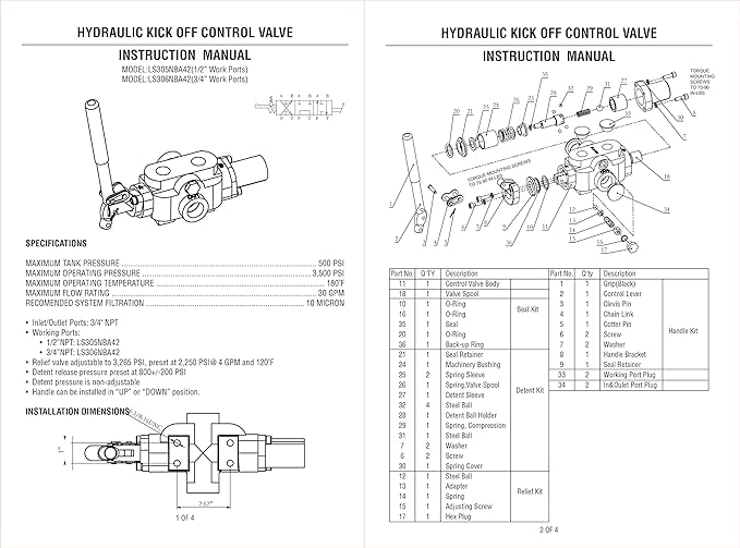
Log Splitter Detent Valve Diagram Dec 18, 2018 · The detent valve in a log splitter is the central assembly where the the diagram will show you which ones go on which side of the detent valve. Log Splitter Valve and Accessories by Energy® Manufacturing I do not believe the detent is adjustable on the Energy brand control valves. ENERGY Manufacturing Company, Inc. 7. Push the #2 valve spool all the way out of the detent end of the valve body. ** NOTE ** these instructions apply to replacing seals in the ENERGY DSKCVA-200 series log splitter valves including part number 0C000908. ENERGY® Manufacturing Company, Inc. Hydraulic Kick Off Control Valve Instruction Manual A detent valve lever can be pushed up or down to put the valve into operation. If you're used to the lever going one way on one log splitter, you might have overlooked the valve position on a different log splitter that works differently. Check the manual to be sure you have proper lever position. Check the pressure going into the detent valve ...
Log splitter detent valve diagram. Hydraulic Kick Off Control Valve Instruction Manual A detent valve lever can be pushed up or down to put the valve into operation. If you're used to the lever going one way on one log splitter, you might have overlooked the valve position on a different log splitter that works differently. Check the manual to be sure you have proper lever position. Check the pressure going into the detent valve ... ENERGY Manufacturing Company, Inc. 7. Push the #2 valve spool all the way out of the detent end of the valve body. ** NOTE ** these instructions apply to replacing seals in the ENERGY DSKCVA-200 series log splitter valves including part number 0C000908. ENERGY® Manufacturing Company, Inc. Log Splitter Detent Valve Diagram Dec 18, 2018 · The detent valve in a log splitter is the central assembly where the the diagram will show you which ones go on which side of the detent valve. Log Splitter Valve and Accessories by Energy® Manufacturing I do not believe the detent is adjustable on the Energy brand control valves.
Hydra Part Log Splitter Valve 80LPM (A&B 1/2" BSP) (P&T 3/4 ...

How to fix the automatic return on a log splitter ...

detent valve products for sale | eBay

Hydraulic Log Splitter Control Valve w/ Return Stroke Detent, 21 GPM
LSP2501 YTL 25T Log Splitter Manual Eng 20180326
Ncrdvalves Ov
Hydraulic Log Splitter Valve, 25GPM, 3500PSI, Adjustable ...

Hydraulic Check Valve | Williams Control Valve | Northern ...

Log Splitter Spool Valve: Detailed Login Instructions| LoginNote
Lever Valve, 45 Liter, Detent, 1 Section, with Pressure Relief Valve PRV 160 to 315 bar
Lever Valve, 45 Liter, Detent, 2 Sections, with Pressure Relief Valve PRV 160 to 315 bar
1 Spool Energy Log Splitter Valve w/Pressure Release Detent
Tech Specifications - P81 Series Euro Log Splitter

RuggedMade 30 GPM Hydraulic Directional Control Valve, Log ...
402.344.4434 • www.brand-hyd.com Specifications: 4-Way ...

Rotary Actuation Directional Control Valves by Energy ...
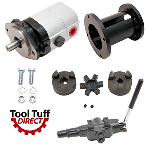
ToolTuff Log Splitter Build Kit: 28 GPM 2-Stage Hydraulic Log ...

Hydraulic Log Splitter Valve, 25 gpm, 3500 psi, Neutral ...

Log Splitter Valve and Accessories by Energy® Manufacturing ...

How to fix the automatic return on a log splitter ...
Model CV Valve Parts | Cross Mfg.
Hydraulic Valve Detent Removal

How to fix the automatic return on a log splitter ...

Hydraulic Valve » CompanyName.com - Super Slogan

Prince Log Splitter Detent Valve - Model Number LS-3000-1
hydraulic log splitter valve for wood cutting machine

Energy Detent Cover Kit for Hydraulic Log Splitter Control ...
Prince hydraulic control valves LOW $$$$$
Speeco 22 ton problem | Hearth.com Forums Home
Model LS3000 Log Splitter

6 Way Solenoid Operated Diverter Valves | HIDROS GROUP

Energy Detent Cover Kit for Hydraulic Log Splitter Control ...

O-Ring Rebuild Kit Hydraulic Control Valve Log Splitter SpeeCo Energy 0A007238 | eBay

Buy Hydraulic Log Splitter Control Valve w/Return Stroke ...
Operation Manual

20 GPM 1 Spool Speeco Log Splitter Valve | Directional ...
To Infinity and power beyond

OEM USA Log Splitter Hydraulic Directional Valve - China Log ...

Prince Log Splitter Detent Valve — Model# LS-3000-1
RuggedMade 30 GPM Hydraulic Directional Control Valve ...
0 Response to "40 log splitter detent valve diagram"
Post a Comment