36 in the diagram to the right the current through
Electrical Meters - APlusPhysics In the diagram at right, an ammeter is connected correctly to measure the current flowing through the circuit. Question: In the electric circuit diagram at right, possible locations of an ammeter and a voltmeter are indicated by circles 1, 2, 3, and 4. PDF Solutions for conceptual questions right through the surrounding loop. As the current in the solenoid increases there is more field and more flux to the right through the loop. There is an induced current in the loop that will oppose the change by creating an induced field and flux to the left. This requires a counterclockwise current when seen from the left end of the solenoid ...
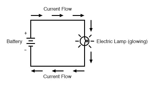
Electric Circuits Review - Printable Version Place ammeters in series at a location such that the current through each resistor can be measured and in a location such that the overall current in the circuit can be measured. On the schematic diagram, use an unbroken arrow to indicate the direction of conventional current.
In the diagram to the right the current through
Electric Circuits Assignment Flashcards Flashcards - Quizlet Use the circuit diagram to decide if the lightbulb will light. Justify your answer. Use the circuit diagram to decide if the lightbulb will light. Justify your answer. ... The branch without the bulb has almost no resistance, so all the current will flow through that branch instead of flowing through the bulb. PDF Circuits Worksheet - Wpmu Dev The diagram to the right represents an electric circuit consisting of four resistors and a 12-volt ... Determine the resistance of resistor R shown in the diagram. Questions 11 through 13 refer to the following: A 3.0-ohm resistor, an unknown resistor, R, and two ammeters, A 1 ... What is the current through each resistor? 3. Resistors R 1, R 2 PDF Chapter 23 Magnetic Flux and Faraday's Law of Induction The current in the wire produces a magnetic field. At point 1 this external field is OUT of the page. At point 2 the external field is INTO the page. This magnetic field passes through the loop and is the source of magnetic flux through the coil. As the loop slides by position 1, the flux through the loop is INCREASING and it is Pointing
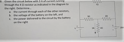
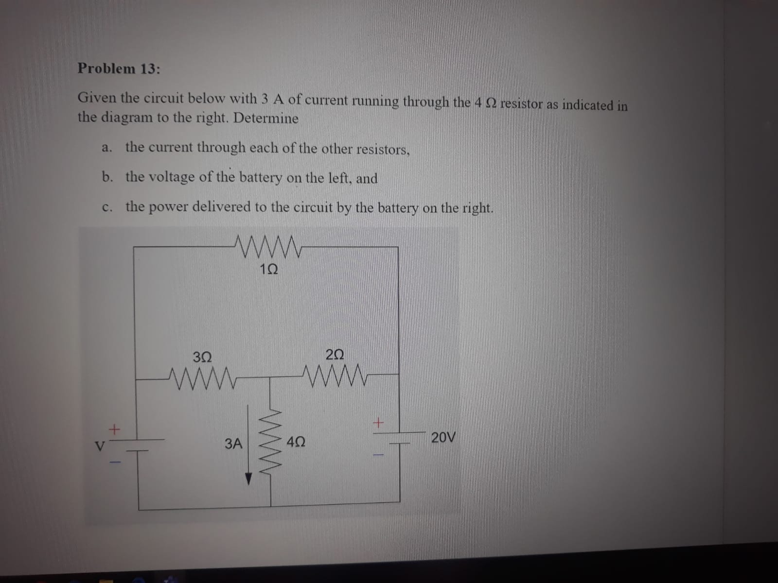
In the diagram to the right the current through. Physics 2 Exam 2 conceptuals Flashcards | Quizlet Use the figure to the right with the information here for questions 1 and 2. A current of 0.15 A flows in a clockwise direction in the rectangular loop shown to the right. The loop dimensions are 0.3 m horizontal length and 0.20 vertical height. The right half of the loop is in a uniform magnetic field of 0.50 T pointing into the paper. Circuits: One Path for Electricity - Lesson - TeachEngineering Feb 22, 2022 · Because the current is the same throughout a series circuit, the voltage drop across each light bulb is directly proportional to that bulb's resistance (by rearranging the Ohm's law equation, V=I*R). Figure 4. A series circuit (left) and the corresponding circuit diagram (right). Kirchhoff's Rules - Practice - The Physics Hypertextbook Given the circuit below with 3 A of current running through the 4 Ω resistor as indicated in the diagram to the right. Determine… the current through each of the other resistors; the voltage of the battery on the left; the power delivered to the circuit by the battery on the right Solved Given the circuit below with 3 A of current running ... Transcribed image text: Given the circuit below with 3 A of current running through the 4 Ω resistor as indicated in the diagram to the right. Determine... 8. 1Ω a. the current through each of the other resistors b. the voltage of the battery on the left, and c. the power delivered to the circuit by the battery 20 32 on the right 20V 3A40 Determine the current through each resistor in the ...
I 01 The diagram to the right shows a straight current ... I 01 The diagram to the right shows a straight current carrying wire near a from PHYSICS 60 at Alabama State University Solved The diagram to the right shows a current through a ... The diagram to the right shows a current through a solenoid sitting in a magnetic field. Relative to the page, how will the coil move due to the magnetic field? v tv B 100 TV O to left to right O to top of page) to bottom rotate clockwise rotate counterclockwise cannot be determined PDF Circuit A Circuit B - Livingston Public Schools current would go down the path of no resistance leaving no current passing through the lamp (short circuit). Questions 9 and 10 refer to the following: A 50.-ohm resistor, an unknown resistor R , a 120-volt source, and an ammeter are connected in a complete Electricity Review-Sheet Name: Date Mar 22, 2013 · 46. In the circuit diagram shown, what is the current through the 4.0-ohm resistor? A. 1.0 ampere B. 0.33 ampere C. 3.0 amperes D. 48 amperes 47. The diagram here shows a resistor of 5 ohms and a resistor of 10 ohms connected in parallel in a circuit. What is the total resistance of the circuit? A. less than 5 ohms B. 5 ohms C. 15 ohms D ...
Solved 8. Given the circuit below with 3 A of current | Chegg.com Given the circuit below with 3 A of current running through the 4 Ω resistor as indicated in the diagram to the right. Determine... 10 a. the current through each of the other resistors, b. the voltage of the battery on the left, and c. the power delivered to the circuit by the batterywwww 20 on the right 20V PDF Magnetic Field & Right Hand Rule Current Loop We have a current, I, going counter-clockwise around in a closed loop. From the right hand rule we can see that in the center of the loop the magnetic field points out of the page. Using the Biot-Savart law The integral over the ring is 2pi R. 1. The diagram below represents magnetic lines of 4. In which ... Jun 02, 2010 · 27. In the diagram at the right, electron current is passed through a solenoid. The north pole of the solenoid is nearest to point (1) A (3) C (2) B (4) D 28. The diagram below shows an electron current in a wire loop. What is the direction of the magnetic field at the center of the loop? (1) out of the page (3) clockwise (2) into the page (4 ... Kirchhoff's rules - University of Tennessee The current flowing through R 3 is I = V/R 3, the current flowing through R 1 and R 2 is V/R 12 = 3 A. General rules for finding the equivalent resistance of a simple circuit: Two (or more) resistors with their heads directly connected together and their tails directly connected together are in parallel.
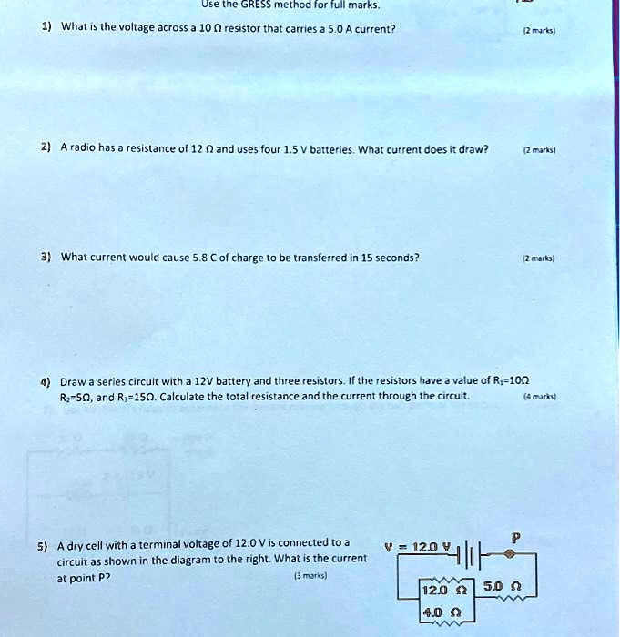
SOLVED:Use tne GRESS mnelhod for iullmarks What is the ...
PDF PSI Physics Electric Current and Circuits Multiple Choice ... 1. The amount of charge flowing through a cross-sectional area of a wire per unit of time is called: A. Voltage B. Power C. Resistance D. Work E. Current 2. What is the direction of the conventional current through the light bulb in the circuit presented by the diagram above?
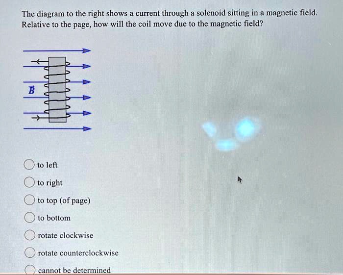
SOLVED:The diagram to the right shows current through ...
PDF Chapter 23 Magnetic Flux and Faraday's Law of Induction The current in the wire produces a magnetic field. At point 1 this external field is OUT of the page. At point 2 the external field is INTO the page. This magnetic field passes through the loop and is the source of magnetic flux through the coil. As the loop slides by position 1, the flux through the loop is INCREASING and it is Pointing
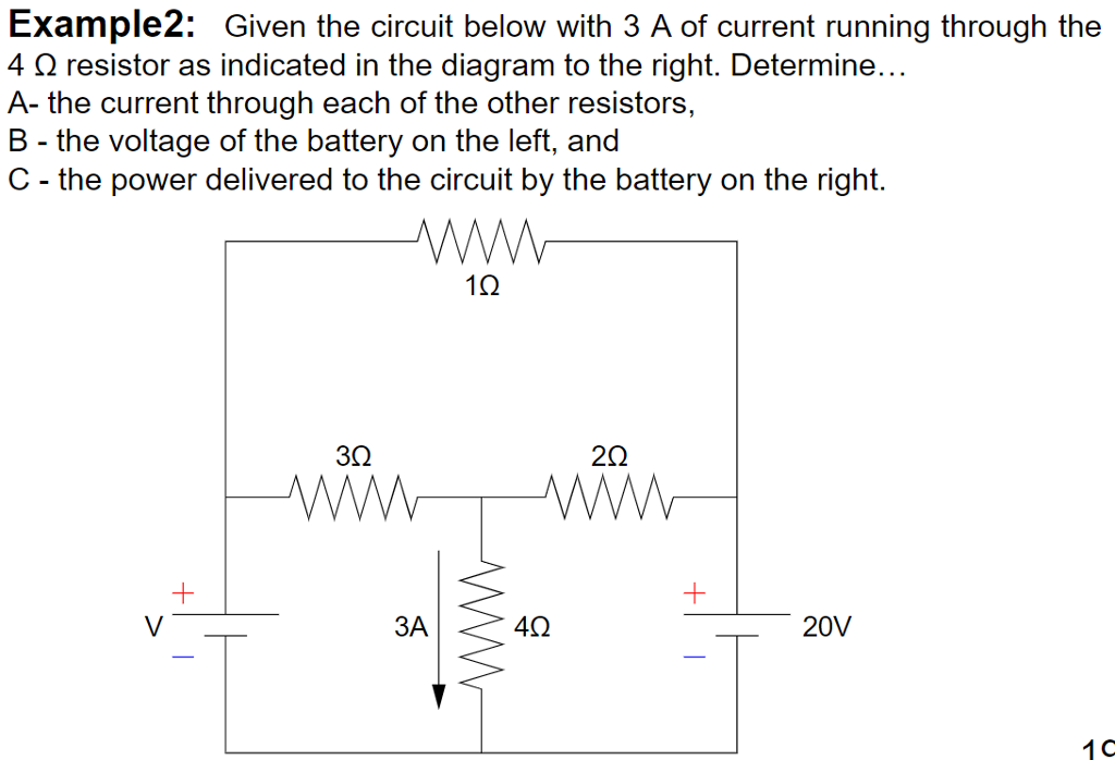
Solved Example2: Given the circuit below with 3 A of current ...
PDF Circuits Worksheet - Wpmu Dev The diagram to the right represents an electric circuit consisting of four resistors and a 12-volt ... Determine the resistance of resistor R shown in the diagram. Questions 11 through 13 refer to the following: A 3.0-ohm resistor, an unknown resistor, R, and two ammeters, A 1 ... What is the current through each resistor? 3. Resistors R 1, R 2
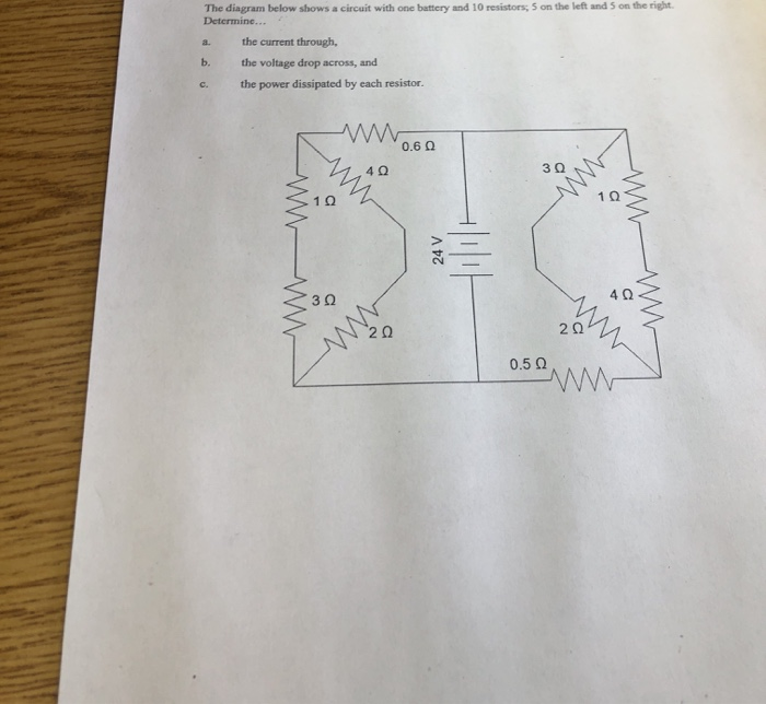
Solved The diagram below shows a circuit with one battery ...
Electric Circuits Assignment Flashcards Flashcards - Quizlet Use the circuit diagram to decide if the lightbulb will light. Justify your answer. Use the circuit diagram to decide if the lightbulb will light. Justify your answer. ... The branch without the bulb has almost no resistance, so all the current will flow through that branch instead of flowing through the bulb.

A current through a horizontal powerline flows in east to west direction. What is the direction ...
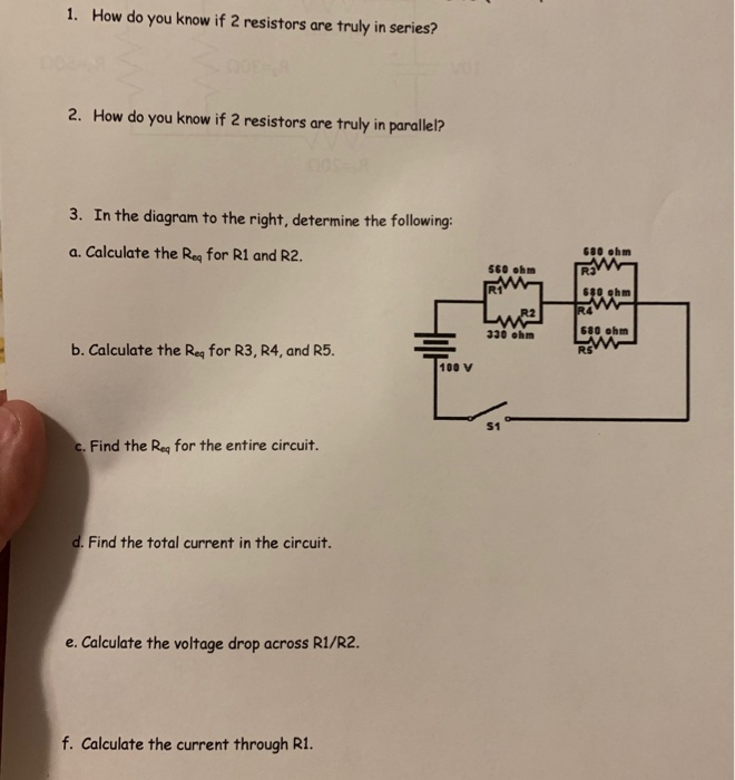
Solved 1. How do you know if 2 resistors are truly in | Chegg.com
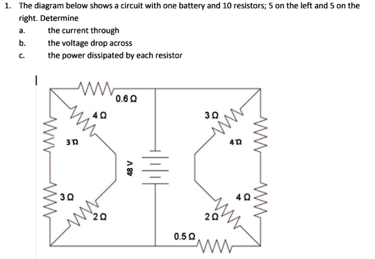
SOLVED:The diagram below shows a circuit with one battery and ...
Solved] Problem solving 1. The diagram below shows a circuit ...
Solved 8. Given the circuit below with 3 A of current | Chegg.com
Electrical news and engineering . osses to be in-vestigated ...

Learn.Digilentinc | Measuring Current Using Digital Multimeters
Resistance | Basic Concepts Of Electricity | Electronics Textbook
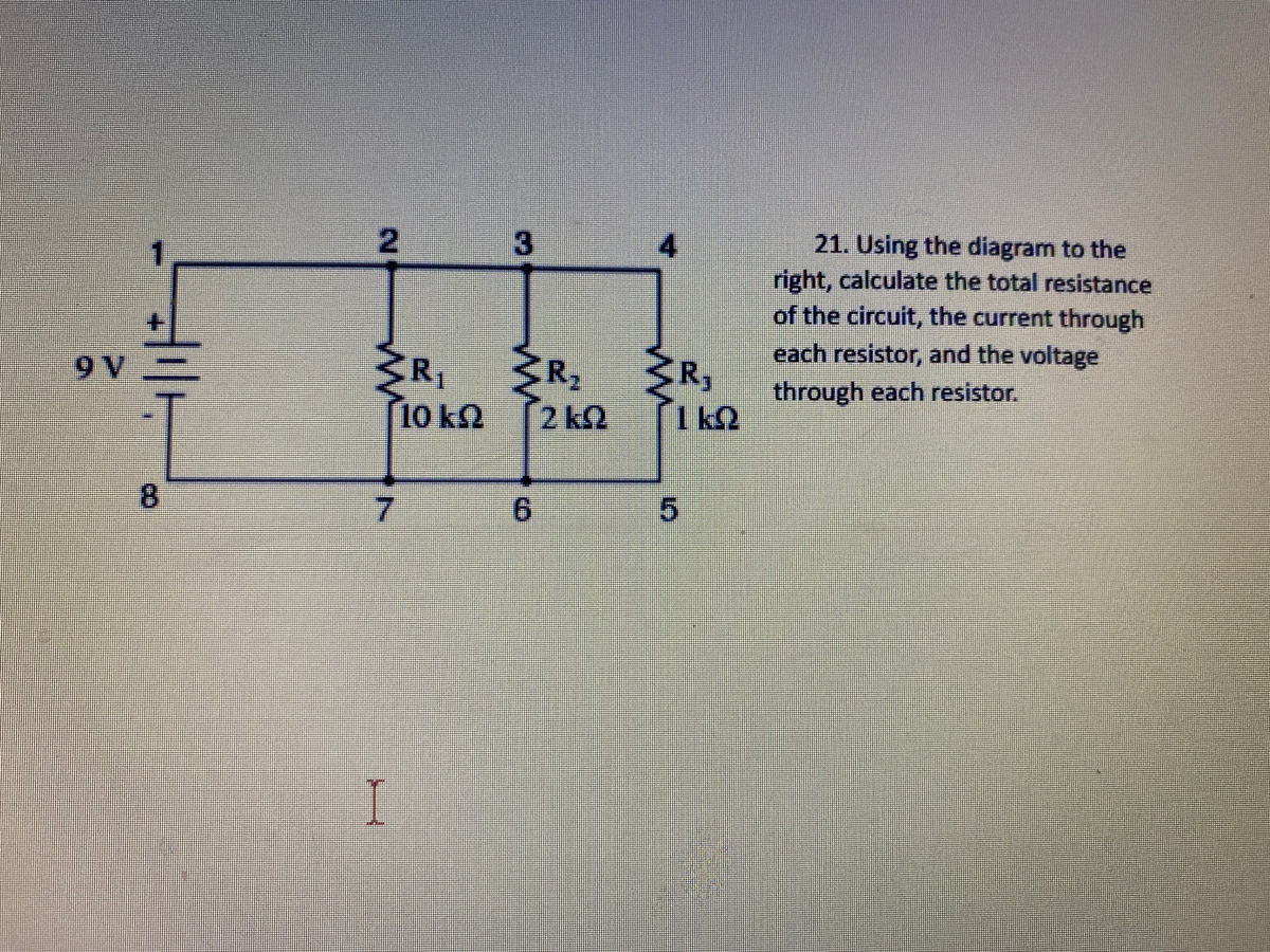
Answered: 3 21. Using the diagram to the right,… | bartleby
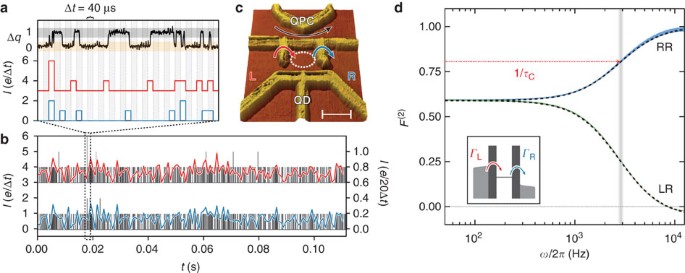
Measurement of finite-frequency current statistics in a ...
94 The diagram at right shows three resistors, R1, R2, and R3
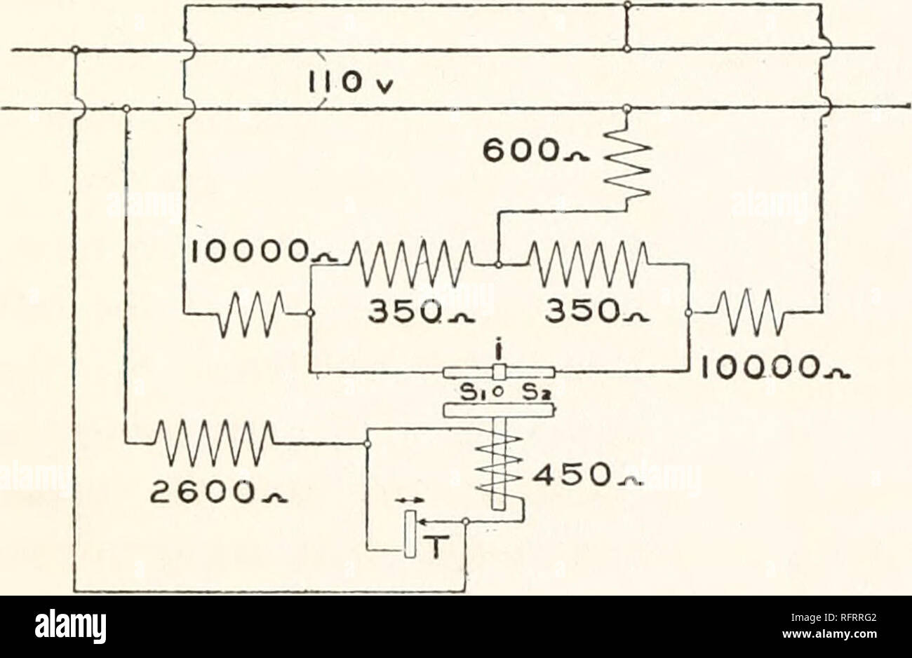
Carnegie Institution of Washington publication. FIG. 21 ...
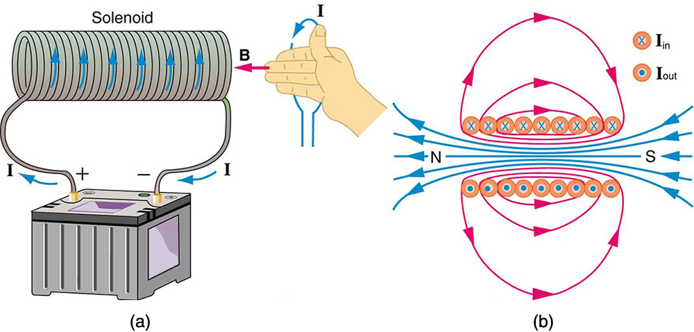
Magnetic Fields Produced by Currents: Ampere's Law | Physics

Will Rate for Correct answer! Thank you. R R2 b On the ...

19.1 Ohm's law | Texas Gateway
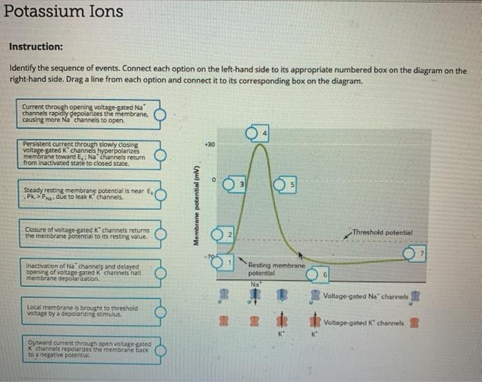
Solved Potassium Ions Instruction: Identify the sequence of ...
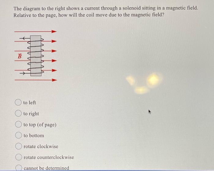
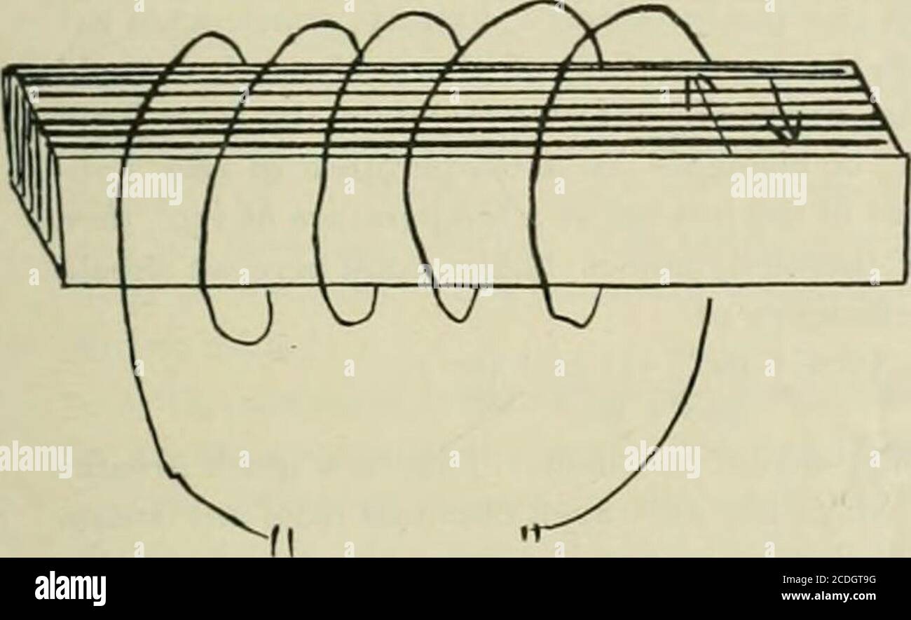
Solved The diagram to the right shows a current through a ...
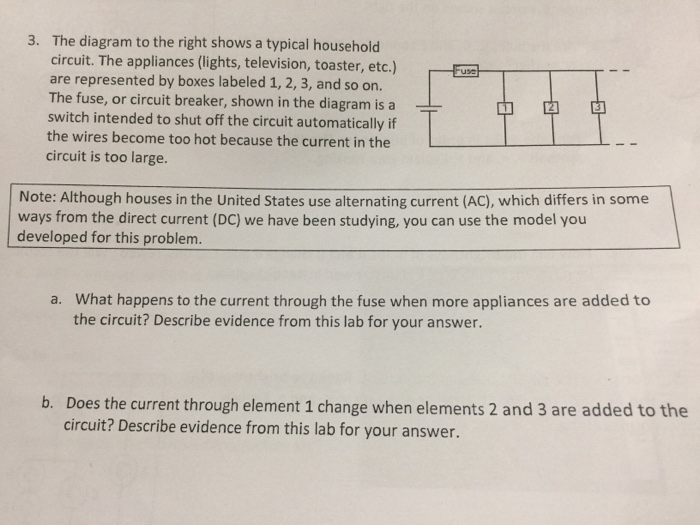
Solved 3. The diagram to the right shows a typical household ...

Capacitors 6
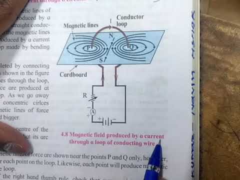
Science 1 magnetic field produced by a current through a loop of conducting wire diagram based quest
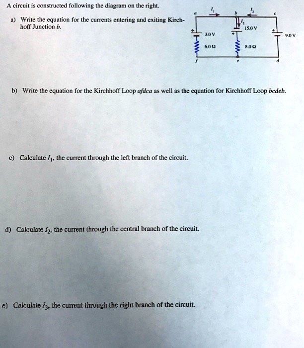
SOLVED:circuit is constructed following the diagram on the ...
Consider the following circuit. How do you obtain the voltage ...

Power Distribution Question - Motors, Mechanics, Power and ...

Given the circuit on right find. The volatage drop across the ...
An elementary manual of radiotelegraphy and radiotelephony ...
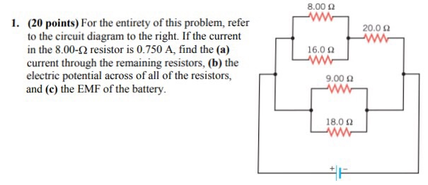
Solved 8.00 Ω (20 points) For the entirety of this problem ...
AP Physics: Chapter 18 Direct Current Circuits

What is the current through the fourth wire shown in the ...
What is the current through 10 ohm resistance on the right of ...
left) Current through the 256 × 256 pixels of the sensor as ...
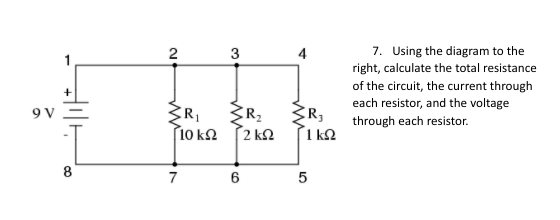
Answered: 2 3 4 7. Using the diagram to the… | bartleby
Answered: Given the circuit below with 3 A of… | bartleby
0 Response to "36 in the diagram to the right the current through"
Post a Comment