37 refrigeration cycle diagram pdf
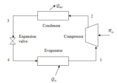
PDF Chapter 11 REFRIGERATION CYCLES REFRIGERATION CYCLE The vapor-compression refrigeration cycle is the ideal model for refrigeration systems. Unlike the reversed Carnot cycle, the refrigerant is vaporized completely before it is compressed and the turbine is replaced with a throttling device. 5 Schematic and T-s diagram for the ideal vapor-compression refrigeration cycle. chapter_11_lecture.pdf - Chapter 1 INTRODUCTION AND ... THE IDEAL VAPOR-COMPRESSION REFRIGERATION CYCLE The vapor-compression refrigeration cycle is the ideal model for refrigeration systems. Unlike the reversed Carnot cycle, the refrigerant is vaporized completely before it is compressed and the turbine is replaced with a throttling device. Schematic and T-s diagram for the ideal vapor-compression ...
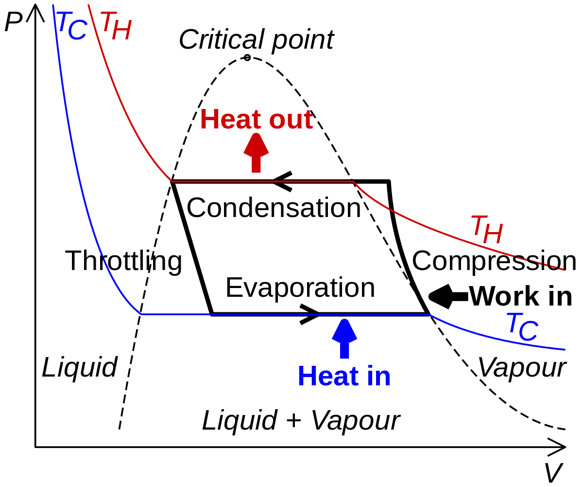
REFRIGERATION CYCLES Figure 2-4: Wet refrigeration Cycle - The expander has been substituted by a throttling valve. If an expander had been used the line from d to a would be a vertical line. This is also done for mechanical reasons. The refrigeration cycles can also be represented in a P-H diagram. Figure 2-5: P-H diagram representation of a dry refrigeration cycle

Refrigeration cycle diagram pdf
PDF Chapter 10 Refrigeration & Heat Pump Cycles (Systems) • If a single refrigeration cycle could be used for the overall temperature range, this would be represented by the cycle 1->a->7->b->1. • Two significant effects are apparent from the Ts diagram: (1) for the single cycle - the compressor work is increase by area 2->a->6->5->2. (2) there is a decrease in the refrigeration capacity when a ... PDF Refrigeration 101 - US EPA Refrigeration Cycle Evaporator Condenser / Receiver Expansion Device. Vapor Compression Cycle. Th MOVEMENT Cooling by the removal of heat The MOVEMENT of HEAT from a place where it is notot a ted to a wanted to a place where it is unobjectionable. How Heat is Removed. What is heat? A form of energy What is cold? PDF Refrigeration & Air-Conditioning - AgriMoon Lesson 1 Basic refrigeration cycle and concepts, standard rating of refrigerating machines 5-8 Lesson 2 Elementary vapour compression refrigeration cycle 9-12 Lesson 3 Representation of Vapour compression Refrigeration cycle on P-V, T- ф and P-H diagrams, Use of refrigerant properties tables and P-H (Mollior) charts. 13-19
Refrigeration cycle diagram pdf. PDF Refrigeration Cycle REFRIGERATION CYCLE The refrigeration cycle shown here is a typical R-22 system. The compressor and thermal expansion valve are the boundaries for the high and low sides. It's important to understand that a refrigerator is a heat engine that operates in reverse. Energy is transferred from a low level to high level, which is contrary to Refrigeration cycle The log p-h diagram shows the thermodynamic state vari- ables in the respective phase. • pressure p. • specific enthalpy h. • temperature T. • specific volume v. PDF Refrigeration - NCSU • Purpose of refrigeration • Examples and applications • Choice of coolant and refrigerants • Phase diagram of water and CO 2 • Vapor compression refrigeration system • Pressure-enthalpy diagram for refrigerants • Refrigerator, air conditioner, thermoelectric cooler, heat pump • Designation, choice, criteria for selection, and Refrigeration Cycle The Reversed Carnot Cycle Actual Vapor‐Compression Refrigeration Cycle Fig. 5-4: T-s diagram for actual vapor-compression cycle. Most of the differences between the ideal and the actual cycles are because of the irreversibilities in various components which are: 1-In practice, the refrigerant enters the compressor at state 1, slightly superheated vapor, ...
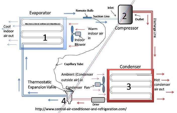
PDF Case 1: The Basics of Refrigeration Cycle P.H. Diagram ... 1-5. This Cogitation is to base on idea simple cycle with no losses. Figure 1-5 Refrigeration Cycle on the P-H Diagram Take the structure image of this refrigeration cycle from Figure 1-5, it becomes the P-H diagram for engineering calculation as shown in Figure 1-6. The points which are required for engineering calculation are from H 1 to H PDF How does basic refrigeration cycle work? This is how the refrigeration cycle diagram looks: Yeah, it seems complicated at first, but it will be easier to understand once I have explained the refrigeration cycle diagram section by section. It important to understand the basic refrigeration cycle, to comprehend what is going on within the air conditioner units, we cannot see it. Chapter 10: Refrigeration Cycles Chapter 10-5 The P-h diagram is another convenient diagram often used to illustrate the refrigeration cycle. The ordinary household refrigerator is a good example of the application of this cycle. Results of First and Second Law Analysis for Steady-Flow PDF UNIT 2 REFRIGERATION CYCLE Refrigeration Cycle Refrigeration cycle is the basis of all refrigeration systems. So refrigeration cycle should be known to understand the refrigeration system. Some basic refrigeration cycles are discussed here through different diagrams. 2.2 VAPOUR COMPRESSION CYCLE Vapour compression cycle is an improved type of air refrigeration cycle in which a suitable ...
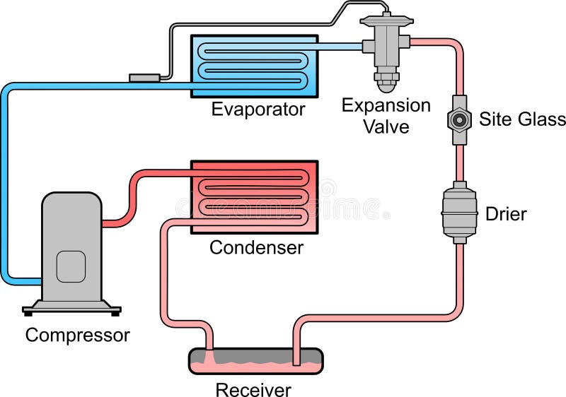
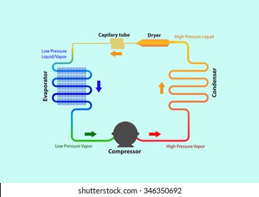
Beginner 1. Basic Refrigeration Cycle.pptx - Squarespace 4 key components needed in a basic refrigera=on cycle: 1. Compressor. 2. Condenser. 3. Evaporator. 4. Metering Device. Refrigeration Cycle ...16 pages REFRIGERATION CYCLES Figure 4: Wet refrigeration Cycle - The expander has been substituted by a throttling valve. If an expander had been used the line from d to a would be a vertical line. This is also done for mechanical reasons. The refrigeration cycles can also be represented in a P-H diagram. Figure 5: P-H diagram representation of a dry refrigeration cycle PDF ENSC 388: Engineering Thermodynamics and Heat Transfer Figure 6- Pressure-enthalpy diagram of an ideal refrigeration cycle. Figure 7- L F D diagram of a real refrigeration cycle. To calculate the refrigerating capacity, i.e., heat transfer from low temperature source, 3 6 Å, the refrigerant mass flow rate I 6 should be known beforehand. The specific volume å for the refrigerant is read from the L PDF Motor Vehicle Air Conditioning (MVAC) System operation and the refrigerant cycle. At Sea level ‐water boils at 212⁰ F ‐R‐134a boils at ‐15⁰ F. At Sea level ‐ ‐R‐134a boils at ‐15⁰ F At 30 psig ‐ ‐R‐134a boils at 35⁰ The Pressure of theF evaporator will control it's Temperature ...
Analysis of A Refrigeration Cycle With Coolprop PDF | PDF ...
PDF Refrigeration: Theory And Applications 1.1 Importance of Refrigeration 8 1.2 A Brief History of Refrigeration 9 1.3 Scope and Outline of this Book 10 1.4 Bibliography for Chapter 1 10 Part 1: Theory 11 2 Thermodynamics12 2.1 Definitions12 2.2 The First Law of Thermodynamics 16 2.3 The Second Law of Thermodynamics 17 2.4 Phase diagrams and refrigerant properties 22

Advantages and Disadvantages of Vapor Compression ...
PDF Basic Knowledge Thermodynamics of the Refrigeration Cycle Carnot cycle, here the enclosed area is a rectangle. This cycle is often used as a comparison cycle to describe the quality of the cyclic process. The direction of the cyclic process in theT-s diagram determines w hether this is a heat pump cycle (refrigeration cycle) or a work machine cycle (steam power cycle). Refrigeration cycles are anti-

Simple Refrigeration Cycle (Hindi/Urdu) - YouTube ...
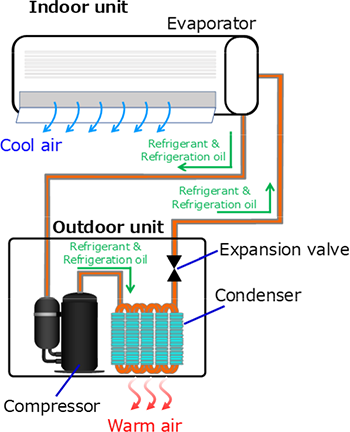
What is Refrigeration Cycle? Basic, Diagram & Explanation ... The refrigeration cycle is the main basic cycle for all air conditioning and refrigeration equipment. In this chapter, we will discuss, basics of a refrigeration cycle, mainly vapor compression cycle, main concept, parts, components, working principle along with a real example, etc.
Nissin Refrigeration & Engineering Ltd. | Product information ...
PDF Unit 5: Refrigeration Systems - IGNOU Figure 5.3 T-S Diagram of Ideal Vapour Compression Refrigeration Cycle 5.6 PRESSURE ENTHALPY DIAGRAM The refrigeration industry did not always have the analysis tools that are available today. For many decades, the manufacturers and technicians relied on the
SECONDARY REFRIGERANT SYSTEMS
PDF Refrigeration & Air-Conditioning - AgriMoon Lesson 1 Basic refrigeration cycle and concepts, standard rating of refrigerating machines 5-8 Lesson 2 Elementary vapour compression refrigeration cycle 9-12 Lesson 3 Representation of Vapour compression Refrigeration cycle on P-V, T- ф and P-H diagrams, Use of refrigerant properties tables and P-H (Mollior) charts. 13-19
![PDF] Experimental analysis of absorption refrigeration system ...](https://d3i71xaburhd42.cloudfront.net/294e14e6d8f4f70bcf575021e67e8261e3b6198e/5-Figure2-1.png)
PDF] Experimental analysis of absorption refrigeration system ...
PDF Refrigeration 101 - US EPA Refrigeration Cycle Evaporator Condenser / Receiver Expansion Device. Vapor Compression Cycle. Th MOVEMENT Cooling by the removal of heat The MOVEMENT of HEAT from a place where it is notot a ted to a wanted to a place where it is unobjectionable. How Heat is Removed. What is heat? A form of energy What is cold?
Chapter 10: Refrigeration Cycles
PDF Chapter 10 Refrigeration & Heat Pump Cycles (Systems) • If a single refrigeration cycle could be used for the overall temperature range, this would be represented by the cycle 1->a->7->b->1. • Two significant effects are apparent from the Ts diagram: (1) for the single cycle - the compressor work is increase by area 2->a->6->5->2. (2) there is a decrease in the refrigeration capacity when a ...
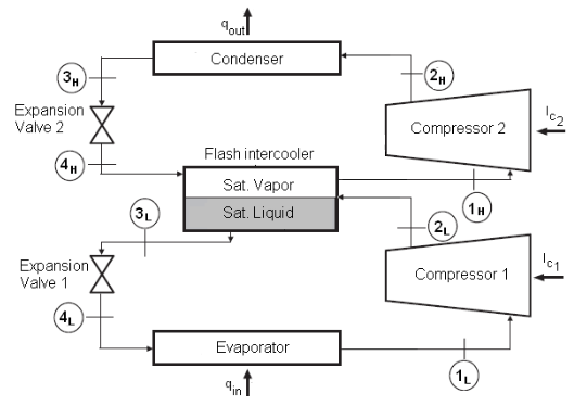
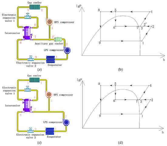
Thermodynamic Calculations of Two-Stage Vapor Compression ...
What is the h-s diagram for vapour compression refrigeration ...
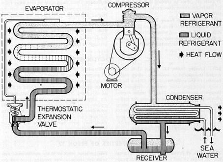
Submarine Refrigeration and Air-Conditioning Systems - Chapter 6
Basic Refrigeration Cycle

Draw a neat sketch of vapour compression refrigeration cycle ...

Planning and engineering data 3. Fish freezing - 3. Processes ...

HVAC - The Refrigeration Cycle - HVAC Beginners
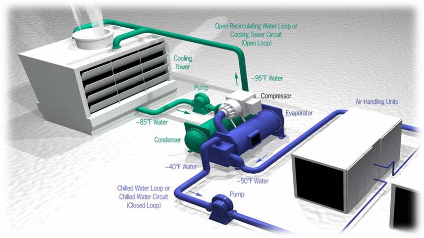
Types of Chiller and Refrigeration Cycles
Performance analysis and development of a refrigeration cycle ...
Solved: A vapor-compression refrigeration cycle has its ...
Vapor-compression refrigeration - Wikipedia
Refrigeration Cycle stock vector. Illustration of cycle ...

Refrigeration Cycles - Mech Engineering: Thermodynamics - UCL ...
Energies | Free Full-Text | Performance Optimizations of the ...

Products

Simple Refrigeration Cycle (Hindi/Urdu) - YouTube ...
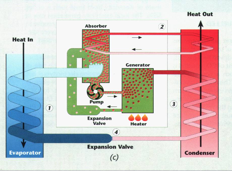
Ammonia Absorption

Refrigerant Pressures, States, And Conditions | Refrigeration ...

Compression Refrigeration Cycle - an overview | ScienceDirect ...

Schematic diagram of a typical vapor compression ...
Refrigeration Cycle Diagram Vector Illustration Stock Vector ...

Refrigeration - Schematic and a Pressure Enthalpy Chart

Two-Phase Fluid Refrigeration - MATLAB & Simulink
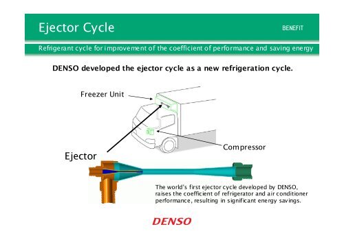
Ejector Cycle(PDF:124KB)
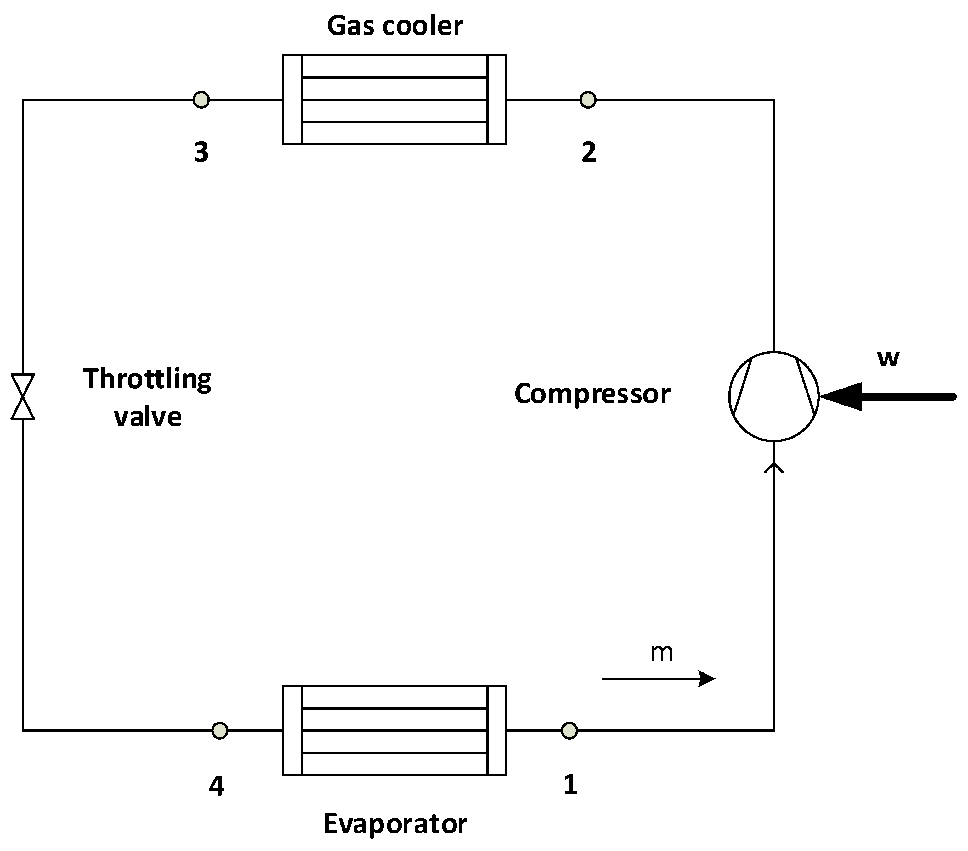
Applied Sciences | Free Full-Text | CO2 Transcritical ...
a ton of refrigeration is equal to

Vapour Absorption Refrigeration system | Working ,Diagram
Refrigeration Oils for Use with Eco-Friendly Refrigerants ...

The Refrigeration Cycle - In easy to understand descriptions ...
How to work vapor compression refrigeration system????? — Steemit
0 Response to "37 refrigeration cycle diagram pdf"
Post a Comment