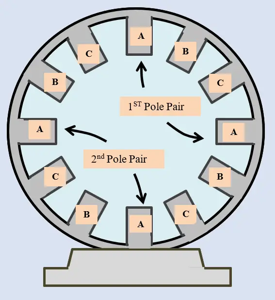
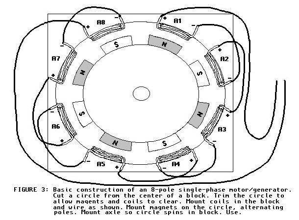
37 single phase generator winding diagram
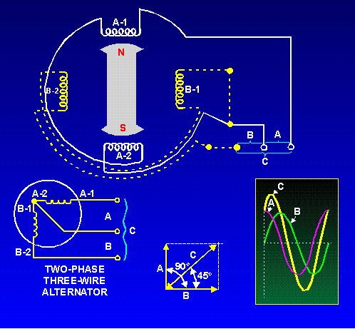
Two-phase electric power - Wikipedia Two-phase electrical power was an early 20th-century polyphase alternating current electric power distribution system. Two circuits were used, with voltage phases differing by one-quarter of a cycle, 90°. Usually circuits used four wires, two for each phase. Less frequently, three wires were used, with a common wire with a larger-diameter conductor. PDF Single Phase Generator Winding Diagram Get Free Single Phase Generator Winding Diagram for connection to the source of power and a rotor winding connected to a commutator. Brushes and commutators are short-circuited and are placed so that the magnetic axis of the rotor winding is inclined to the magnetic axis
Three-Phase Transformer - Basics and Connection Methods Three-phase transformers functions just like three single-phase transformers. But a single three-phase transformer occupies less volume and weighs less than three single-phase transformers designed for the same purpose. It is an electromagnetic energy converting device that has no moving parts and two (or more) windings fixed relative to each other, intended to transfer …

Single phase generator winding diagram
Single phase AC generator - Principle, Construction ... Single phase AC generator. In a single phase AC generator, the armature conductors are connected in series so as to form a single circuit which generates a single-phase alternating emf and hence it is called single-phase alternator. The simplified version of a AC generator is discussed here. (PDF) Three Phase AC Double Layer Wave Winding Diagram, a ... Three Phase AC Double Layer Wave Winding Diagram, a Simplified Method. September 2017. DOI: 10.9790/9622-0709042931. Project: Short Term Load Forecasting. Authors: Kuldeep Shiruru. Jain University ... Single Phase Electric Motor Diagrams A Repulsion Electric Motor is by definition a single phase motor which has a stator winding arranged for connection to the source of power and a rotor winding connected to a commutator. Brushes and commutators are short-circuited and are placed so that the magnetic axis of the rotor winding is inclined to the magnetic axis of the stator winding.
Single phase generator winding diagram. Motor Winding Connection Diagram» All Motor Winding ... 6 Single Phase Motor Connection Diagram. 7 A Class Ceiling Fan Connection Diagram. 7.1 Three Wire Ceiling Fan Connection Diagram With Capactitor. 7.2 Cooler Motor Connection Diagram Video Watch Here:-7.3 Three Phase induction motor winding connection with diagram; 7.4 Star Delta Connection Diagram Of Three-Phase Motor Winding. PDF 2. Generator Basics IEEE - IEEE Region 5 Main Stator: Three Phase • Three windings. • For each phase, there is one group (one or more coils) for each rotor pole. - A group is interconnected - Can be considered as one large coil. • The leads are typically wye (star) connected. The neutral is usually connected to ground or brought out with single-phase loads. 2 poles 6 groups Synchronous Motors: Applications And Working Principle 22/07/2013 · Based on the type of input we have classified it into single phase and 3 phase motors. ... The 3 phase stator winding carrying 3 phase currents produces 3 phase rotating magnetic flux. The rotor carrying DC supply also produces a constant flux. Considering the 50 Hz power frequency, from the above relation we can see that the 3 phase rotating flux rotates … Single Phase 4 Pole Induction Motor Winding Diagram ... 36 slot motor winding diagram madcomics no 15 reading a winding diagram simulation technology for electromechanical design jmag ac motor winding generator series courseware pengky types of single phase induction motors split capacitor start run electrical4u. Whats people lookup in this blog: Single Phase 4 Pole Induction Motor Winding Diagram
PDF Single Phase Generator Winding Diagram Get Free Single Phase Generator Winding Diagram for connection to the source of power and a rotor winding connected to a commutator. Brushes and commutators are short-circuited and are placed so... PDF GENERATOR WIRING DIAGRAM - Multiquip Inc generator wiring diagram 125: 125 mm2 100: 100 mm2 80: 80 mm2 22: 22 mm2 14: 14 mm2 mm2 b l br g gr v p black blue brown green gray violet pink r w y lb lg o red white yellow light blue light green orange wire size code/wire color 5.5: 5.5 mm2 8: 8 mm2 no mark wire size: 1.25 connector arrangement (wiring view) 32 1 w1 v1 u1 u2 v2 cn1 cn2 b4 b ... Why does a delta/wye transformer make 30 degrees phase ... 20/09/2015 · For an ideal single-phase two-winding transformer ... When a two-winding three-phase transformer is modeled as a bank of three single-phase transformers, you can use the previous transforming equations for single-phase transformer, however, you must bear in mind that a winding on one side only affects the corresponding winding on the other side. You … 4 Pole Single Phase Motor Winding Diagram | Webmotor.org Jul 16, 2021 · Winding Setup For A 36 Slot 4 Pole Squirrel Cage Induction Motor Scientific Diagram. Types Of Single Phase Induction Motors Split Capacitor Start Run Electrical4u. 4 Pole Single Phase Ac Motor Wiring Electric Motors Generators Engineering Eng Tips. Schematic Of 36 Slot 4 Pole Stator Winding Generated With The Bobisoft Scientific Diagram.
PDF AC Electrical Generators - Brown University the winding can thus be controlled by controlling the amount of current passing through the conductor causing the magnetic field. The three- phase generator is basically three separate generators in one casing. It has three completely separate windings in which current is produced, but a single rotating magnetic field. Generator Winding How To Single Phase Generator Winding Full ... Generator Winding How To Single Phase Generator Winding Full Winding Formula #generator#energy#winding# 5 essential steps to know single phase generators - Linquip Single phase generator Winding diagram. winding diagram of this product may help you to see where exactly the components rest in the housing and how they cooperate as a system. So we put a PDF file below to make it easier to understand what we mentioned earlier in two previous sections. PDF CONNECTION DIAGRAMS - Absolute Generators CONNECTION DIAGRAMS The following are the most common connection arrangements utilized with Mecc Alte generators. Always verify that the connections of all the leads from the main stator are consistent with the nameplate voltage required. Connection diagrams are supplied with every generator and should be used as the primary source of information.
electric generator - Stator windings | Britannica
PDF Single Phase Generator Winding Diagram Single Phase Generator Winding Diagram Author: sso.bplgroup.com-2022-03-23T00:00:00+00:01 Subject: Single Phase Generator Winding Diagram Keywords: single, phase, generator, winding, diagram Created Date: 3/23/2022 11:11:29 AM
Three-Phase AC Generator Working | Electrical Academia
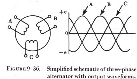
Three-Phase Generator - an overview | ScienceDirect Topics A balanced three-phase generator has three distinct windings, each of which generate alternating e.m.f.s of equal magnitudes. The three e.m.f.s are mutually displaced in phase by 120°, a vector diagram for the set being illustrated in Fig. 8.1.Three-phase generators are cheaper to construct than single-phase generators of the same power rating.
Polyphase Motor/Generator Page
single phase generator wiring diagram - Wiring Diagram May 07, 2017 · Small Sel Generators Wiring Diagrams. Single phase induction generator small sel generators wiring diagrams transfer switches residential manual changeover switch diagram self excited coil 750kv mcr temperature rise china 3p 630a ats 208v and 3 can ac principle franklin electric polyphase motor page house alternators or three power 240 volt 7 wires 5kw avr consultation airing brushless kutai ...

Electric Motors Symbols - AC/DC, Single Phase / Three Phase ...
Autotransformer Connection Explained | EEP 17/12/2020 · Autotransformer consists of a single winding around an iron core, which creates a change in voltage from one end to the other. In other words, the self-inductance of the winding around the core changes the voltage potential, but there is no isolation of the high and low voltage ends of the winding. So any noise or other voltage anomaly coming in on one side is passed …
Solved 3. a) Examine whether a single phase induction motor ...
Single Phase Generator Winding Diagram Single Phase Examples 240/120 240 V winding with a center tap 240x120 Two part winding that can be Generator Step up transformer I V Step down transformer V I Phase diagram c WYE-WYE CONNECTION Lesson 11_et332b.pptx 16 H 1 H 2 X 3 2 1 H 1 H 2 X 3 2 1

Aircraft Electronics and Electrical Systems:
Single Phase Generator Winding Diagram Single Phase Examples 240/120 240 V winding with a center tap 240x120 Two part winding that can be Generator Step up transformer I V Step down transformer V I Phase diagram c WYE-WYE CONNECTION Lesson 11_et332b.pptx 16 H 1 H 2 X 3 2 1 H 1 H 2

Connection diagram of the single-phase induction generator ...
Generator Avr Connection Diagram - Wiring Diagram and ... China Single Phase Generator Avr Circuit Diagram R448 Card For Sel Engine. Automatic Voltage Regulator Avr Analyzer Homemade Circuit Projects. Briggs And Stratton Power Products 030291 0 Promax 9000ea Continental Parts Diagram For Panel Wiring Sincro Ek R Avr. Kavr H4 Kirloskar Generator Voltage Regulator For 240 V Ac Id 21530788388.

Cross section view of single-phase reluctance generator ...
single phase generator diagram&winding full formula ... generator diagram&winding full formula satting , how to make g experiment, generator wiring diagram, how to
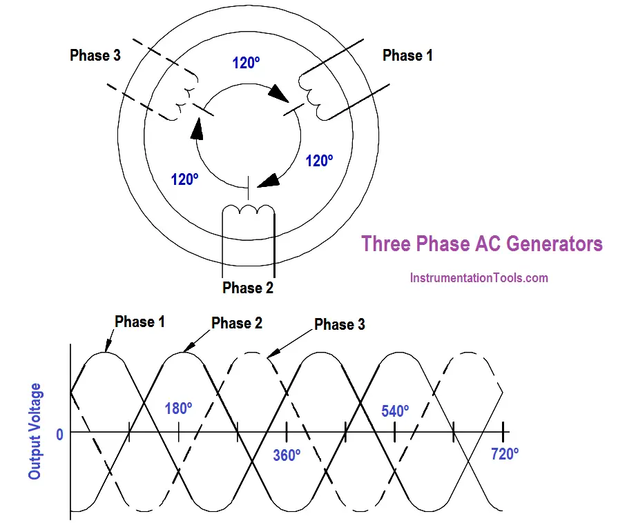
Three Phase AC Generators - Inst Tools
Single-phase generator - Wikipedia Single-phase generator (also known as single-phase alternator) is an alternating current electrical generator that produces a single, continuously alternating voltage. Single-phase generators can be used to generate power in single-phase electric power systems. However, polyphase generators are generally used to deliver power in three-phase distribution system and the current is converted to ...
THEORY, CONSTRUCTION, AND OPERATION
Electrical Technology | All About Electrical & Electronics ... A Very Useful Blog About Electrical & Electronics Engineering & Technology. Electrical Technology | All About Electrical & Electronics Engnieering Electrical Wiring- EE-Calculator, EE Q-A, EE Notes, Motors, Power System, Control

Single-phase generator - Wikiwand
Types of AC Generators - Single Phase and Three Phase AC ... The circular frame of the single phase AC generator is called yoke. The yoke of single phase AC generator is usually made of solid cast steel. The yoke increases the mechanical strength of the generator. It also provides path to the magnetic flux produced by the field winding. Working of Single Phase AC Generator
ALTERNATORS
Mecc Alte Generator Wiring Diagram Mecc Alte ECP series is 1 or 3 phase, brushless, RPM, AVR controlled generator with Aux Winding. It can power from 8kVA to kVA. Dec 14, · A friend has a small diesel generator that he and I have been restoring. Its maybe 10 years old and looks like it is built to survive an atomic explosion. We got it . the relevant diagram in figure 7.
How to Apply Single-phase Power Supply to Three-phase Power ...
Connection diagram of the single-phase induction generator. 3-phase cage induction machines, operated in two series-connected and one-isolated (TSCAOI) winding configuration, have been proposed to generate standalone single-phase electricity at variable ...
Single-phase alternators
Single Phase Generator Winding Diagram Single Phase Generator Winding Diagram Author: secmail.aws.org-2021-05-23T00:00:00+00:01 Subject: Single Phase Generator Winding Diagram Keywords: single, phase, generator, winding, diagram Created Date: 5/23/2021 8:31:30 AM

Single Phase Motor schematics and working | electricaleasy.com
Single-phase generator - Wikiwand Single-phase generator is an alternating current electrical generator that produces a single, continuously alternating voltage. Single-phase generators can be used to generate power in single-phase electric power systems. However, polyphase generators are generally used to deliver power in three-phase distribution system and the current is converted to single-phase near the single-phase loads ...

Armature Winding of Alternator | Electrical4U
TERMINAL MARKINGS AND INTERNAL WIRING DIAGRAMS SINGLE PHASE ... The alternating-current windings of two-phase alternating-current generators and synchronous motors shall have terminal markings as given in MG 1-2.66 for two-phase single-speed induction motors.* The alternating-current windings of single-phase alternating-current generators and synchronous motors
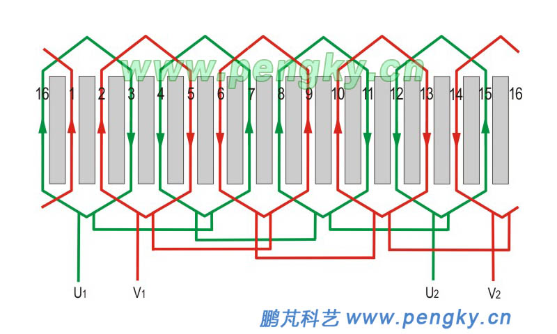
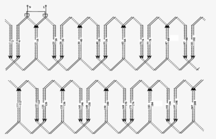
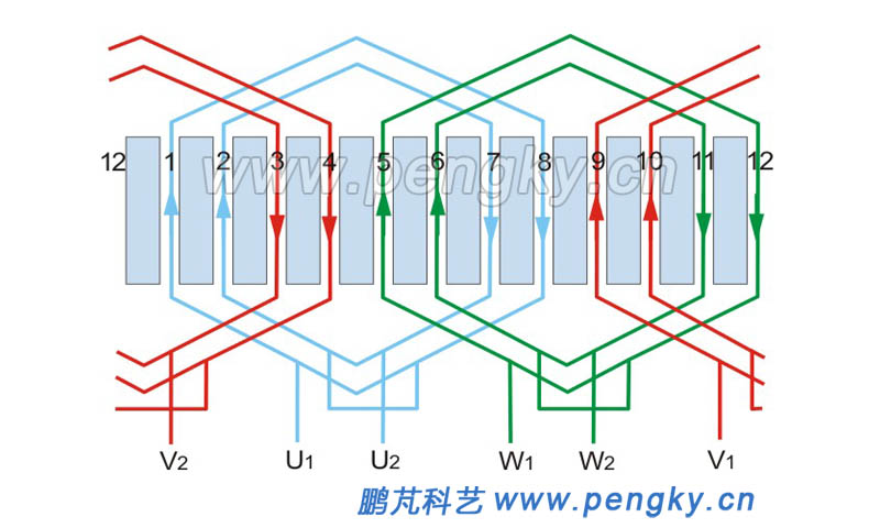
AC Motor Winding | Generator Series Courseware | Pengky
What is Single Phase Generator? Working, Construction ... The working of an elementary 2-pole single-phase alternator shown in Fig. 1. Fig. 1: An elementary single-phase alternator with two poles. Construction of Single Phase Generator. It consists of a single turn rectangular coil (AB) made up of some conducting material like copper or aluminium.
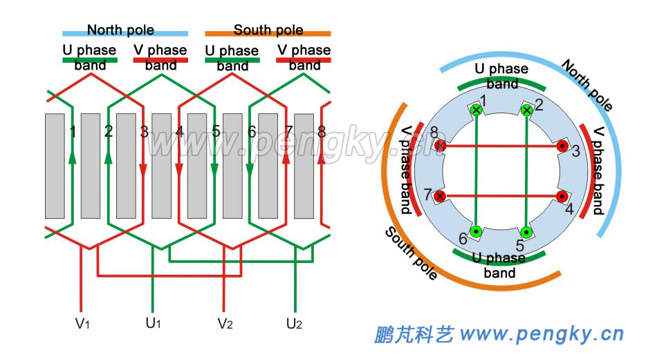
AC Motor Winding | Generator Series Courseware | Pengky
Single Phase Electric Motor Diagrams A Repulsion Electric Motor is by definition a single phase motor which has a stator winding arranged for connection to the source of power and a rotor winding connected to a commutator. Brushes and commutators are short-circuited and are placed so that the magnetic axis of the rotor winding is inclined to the magnetic axis of the stator winding.
AGN 154 - Single Phase Loading for Re- Connectable 3-Phase ...
(PDF) Three Phase AC Double Layer Wave Winding Diagram, a ... Three Phase AC Double Layer Wave Winding Diagram, a Simplified Method. September 2017. DOI: 10.9790/9622-0709042931. Project: Short Term Load Forecasting. Authors: Kuldeep Shiruru. Jain University ...

Single-phase generator - Wikipedia
Single phase AC generator - Principle, Construction ... Single phase AC generator. In a single phase AC generator, the armature conductors are connected in series so as to form a single circuit which generates a single-phase alternating emf and hence it is called single-phase alternator. The simplified version of a AC generator is discussed here.

single phase generator diagram&winding full formula setting, 2 kw,3 kw,5 kw,7.5 kw,10kw
torque - Three-phase versus single-phase operation of a ...

Single-phase generator - Wikipedia
AC Electrical Generators
Single Phase Generator Winding Diagram, HD Png Download ...
Small diesel generators wiring diagrams
AGN 154 - Single Phase Loading for Re- Connectable 3-Phase ...
Three-phase AC motors winding | Generator Series Courseware ...

Two-phase electric power - Wikipedia

Electrical Winding - wiring Diagrams: June 2014
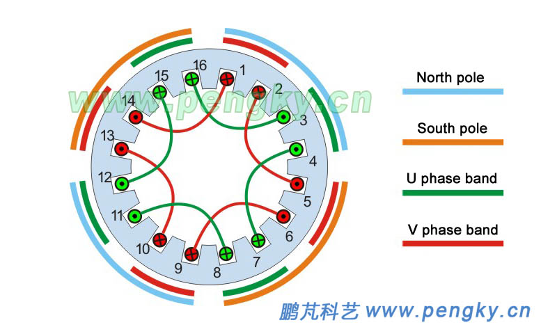
AC Motor Winding | Generator Series Courseware | Pengky

Types of Single Phase Induction Motors- Applications

Connection diagram of the self-regulated self-excited single ...

Motor vehicle, Dynamo, Generator, Starter
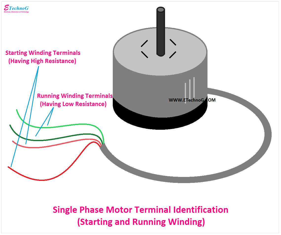
Single Phase Motor Connection Diagram and Wiring Procedure ...

Three-Phase Generator - an overview | ScienceDirect Topics

Single-phase generator - Wikipedia
0 Response to "37 single phase generator winding diagram"
Post a Comment