36 nos relay wiring diagram
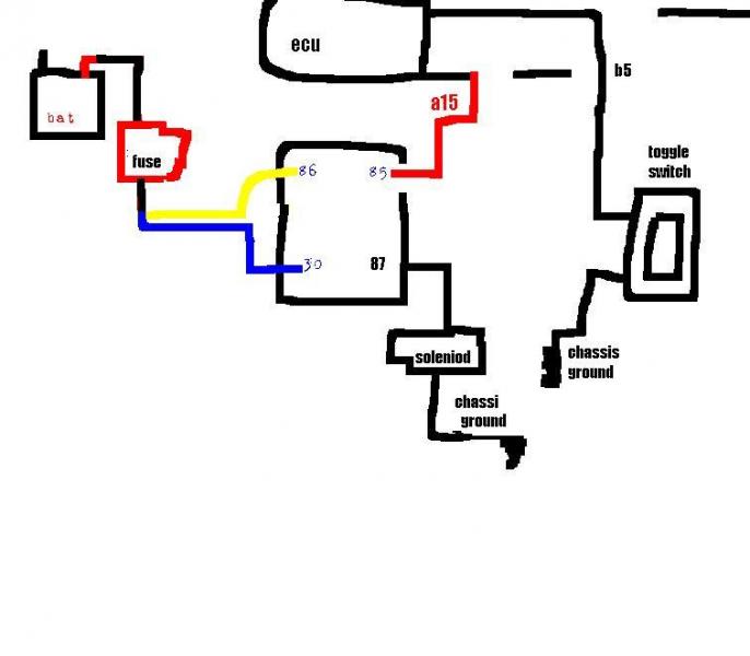
Wiring Electrical Relays Into A Nitrous System - Tech ... Wiring multiple-stage nitrous systems and timing-retard devices can become quite confusing, so to simplify our wiring schematic, we'll look at a single-stage system without any external devices. Nitrous/Retard/Window Switch/Relay Wiring Diagram You have three activation wires for that unit, brown, orange and grey. Those would go to the positive side of the nitrous solenoid. Whenever those wires see 12 volts, the retard will activate and pull out the desired timing based upon the value of retard chip you have plugged into the socket.
Remcon Wiring Diagram I wired it according to the the diagram which was the same as the orignal relay wiring. The relay is in an outlet box (the wall switch controls the outlet for a lamp) and pushed into the box to ground it, I assume. Remcon Low Voltage Relays - RS / RCS Low Voltage Relays.
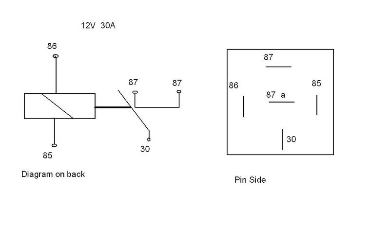
Nos relay wiring diagram
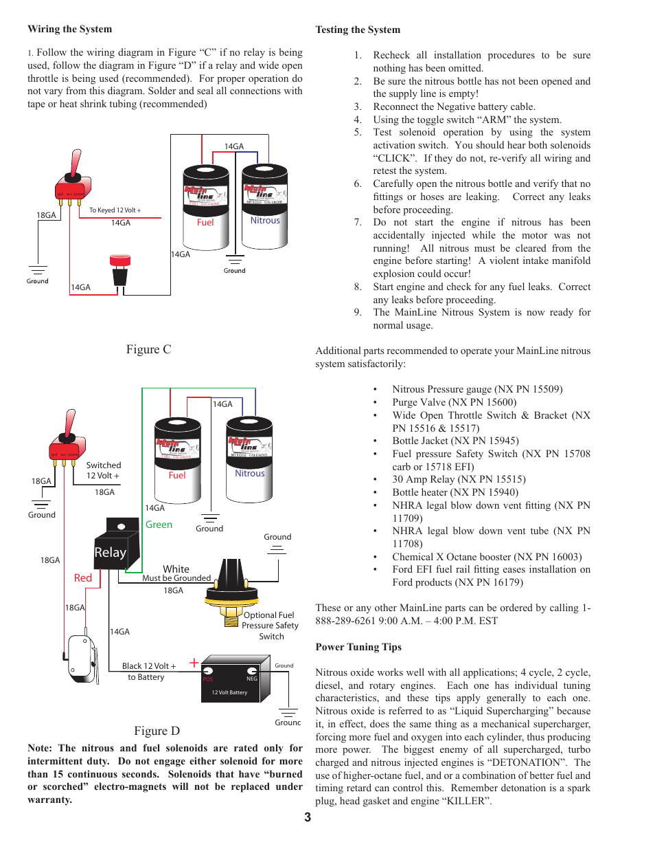
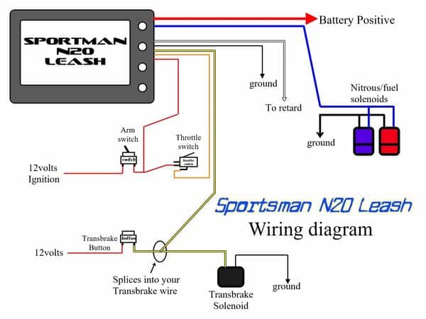
Nitrous And Transbrake Wiring Diagram Wiring your nitrous kit has NEVER been so easy! connect you 12volt power from your throttle switch or manual nitrous button, connect you transbrake or clutch 12volt signal for nitrous safety so that Check out the wiring diagram in the pics. The stud labeled "2" is for the transbrake. It is activated by applying +12volts. Wiring Diagrams - FuelTech USA Wiring Diagrams FT450 Honda K20-24Version: 1.0 | Size: 0.92 MB FT550 8 Cyl Smart CoilVersion: 1.0 | Size: 0.52 MB FT550 6 Cyl Smart CoilVersion: 1.0 | Size: 0.51 MB ... Nitrous Relay Wiring Diagram Also, stick to Hondata's wiring diagram. DO NOT look up relay wiring diagrams on the. OBD1 Honda ECU Nitrous Setup Guide for Hondata S and Neptune Print along with the wiring diagram for the nitrous output and relay. Follow the wiring diagram in Figure "C" if no relay is being. used, follow the diagram in Figure "D" if a relay and.
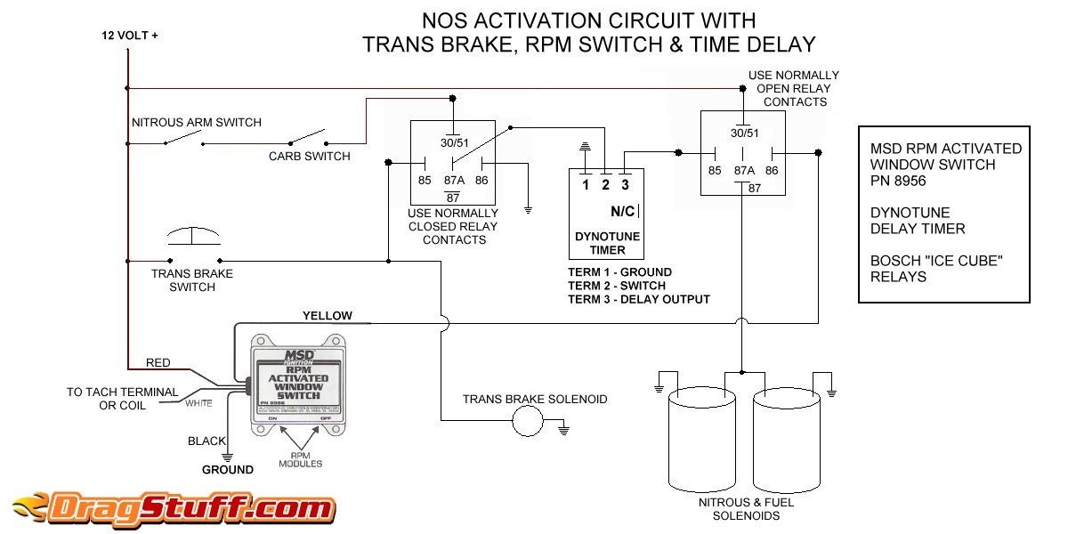
Nos relay wiring diagram. PDF WIRING DIAGRAM FOR N2O WITH TRANSBRAKE ... - Nitrous Supply WIRING DIAGRAM FOR N 2O WITH TRANSBRAKE NOS P/N 15838 NOS P/N 15618 NOTES: 1) Bottom view of all relays 2) All relays must be diode suppressed N4~N 2O N4~N 2O N/C N/O COM TRIG GND 12 Volt from Transbrake Battery Ground 87 87A 30 86 85 Fused and Switched 12 Volts lts Micro Switch Arming Switch Holley Single Relay Transbrake Bump Wiring Diagram SEE REVERSE SIDE FOR WIRING DIAGRAMS -- OPERATtON 1) Set the pushbutton thumbwheels to the desired delay setting. 2) Use your line lock button to do your burnout (if used). 3) If you need to engage the transbrake to back-up the car, do so with the safety switch set to "No Delay".Bump box for 1 wire Transbrakes on the cheap? bodycoach-online.de › onan-carb-parts-diagramOnan carb parts diagram - bodycoach-online.de A wiring diagram usually provides details regarding the… Feb 01, 2020 · Rebuilding my B48M and the DD 14 carburetor has a crack in the bowl side I have my hands on a nearly new Nikki (146-0496) carb from a P series (P216 or P218), but the mount to the intake manifold is different. Wiring Diagrams - Nitrous Outlet These Wiring Diagrams will help you wire up your Nitrous System or Nitrous Accessory. Includes Nitrous Purge, Nitrous Bottle Heater, and Dedicated Fuel System. Your #1 Source for everything Nitrous. Dealer Locator Account. Toggle navigation 254-848-4300 Speak with a Nitrous Expert M-F 8:30am - 5:30pm CST Call or Text Today! ...
PDF SOLID STATE RELAY KIT P/N 15620NOS Installation ... - Holley power all devices being switched ON by the relay. 6. Connect the remaining Blue wire to the device, such as nitrous and fuel solenoids, you wish to turn ON with the relay. 7. It is advisable to connect an in-line fuse holder, or circuit breaker between the relay and the power source of a suitable capacity to protect the relay PDF NOS Nelson2 - Nitrous Supply Title: NOS_Nelson2.doc Author: Gecko Created Date: 1/11/2004 3:58:16 PM Nitrous System Wiring Diagrams - Dragstuff Nitrous Wiring Diagrams. by John Heard Last Updated Jan 4, 2015. Single Stage NOS System with Transbrake Interrupt Relay. Single Stage NOS System with Transbrake Interrupt Relay, MSD Window Switch, and Dynotune Delay Timer. Single Stage NOS System with Transbrake Interrupt (No Relay), MSD Window Switch, and Dynotune Delay Timer. Single Stage ... Nitrous Oxide Wet Kit wiring Diagram Snowmobile nitrous kits are the best way to make big power! More affordable than boondockers or bossnoss. Nitrous Oxide Kits Systems and components are the quickest and easiest way to get large horsepower increases with a minimum of engine modifications and expense. Nitrous Kits offer serious horsepower at the flip of a switch.
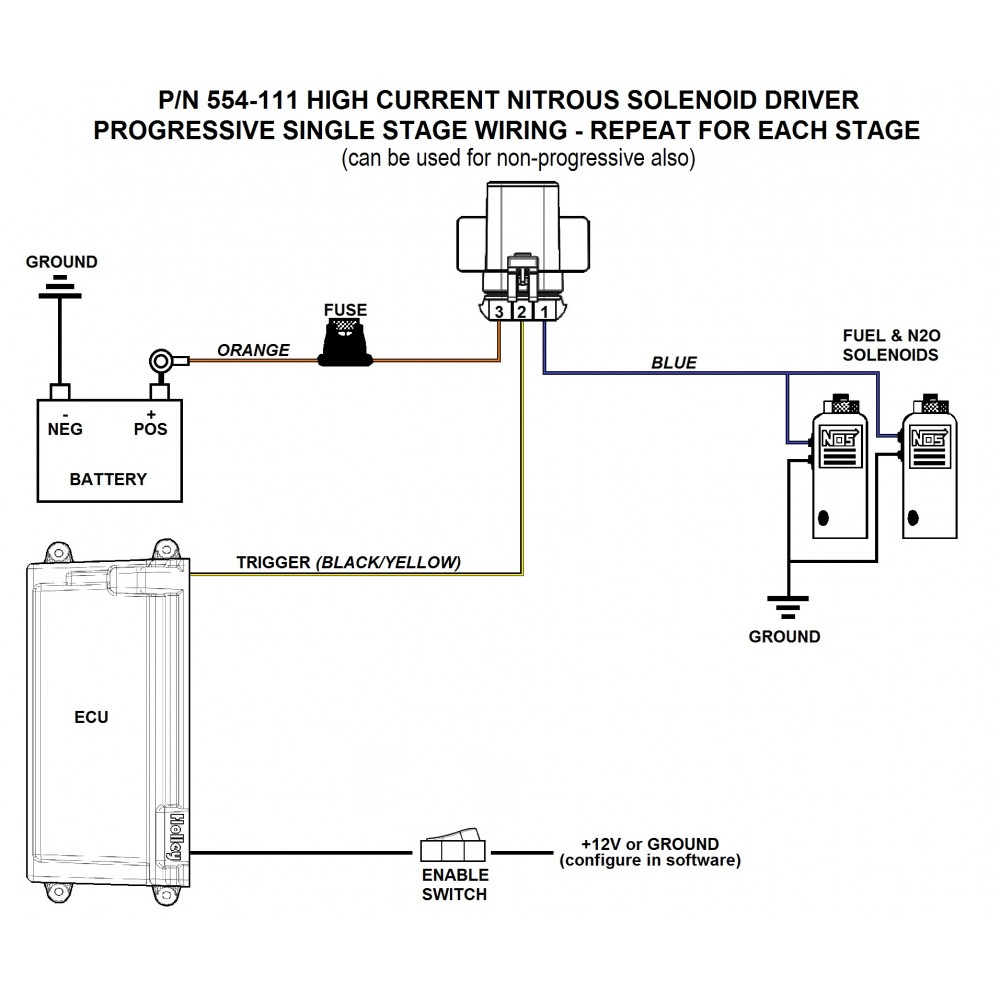
PDF Caution - EXTREME DANGER - Nitrous Express existing NX relay and plug the Max EZ male plug into your NX relay harness. If your nitrous system does not have a standard NX relay harness, use the included NX relay harness to complete the installation. The following diagrams show installation with popular accessories. Select the appropriate diagram Using Holley 554-111 Solenoid Drivers With NOS Progressive ... Hi all. I have an NOS 8 Fogger Sportsman system with a NOS Progressive Launcher, and also a bottle heater. I've wired everything up, except for the relay trigger cable. I bought two Holley 554-111 high current nitrous solenoid drivers, one for each pair of solenoids. The power is connected to both relays with their output wires connected to the solenoids. navy-radio.com › newwww.navy-radio.com - What's New? Aug 2010 - Model 28RT Reperforator-Transmitter - added wiring diagram, manuals, more photos Aug 2010 - Teletype Equipment - added photos and info on AN/FGC-9 (Model 19ASR) Jul 2010 - QSL Cards - Ham Radio and COMMSTA cards andalusienmarkt.deKundli - andalusienmarkt.de Y: Feb 10, 2020 · Briggs Wiring Diagram 12 Up – Wiring Data Diagram – Briggs And Stratton Wiring Diagram 16 Hp Wiring Diagram contains several detailed illustrations that show the connection of various things. Prije 2 godina. 5hp engine. Replacement Petrol Engine 168F / Air Cooled 4 Stroke 6.
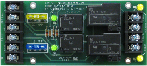
NITROUS RELAY BOARDS - Digital Delay Digital Delay's line of Nitrous Relay Boards are designed to work hand in hand with our Delay Boxes to simplify wiring. All versions of our Nitrous Relay Boards have fused outputs, status indicators, and additional inputs for the Wide Open Throttle Switch and an Override button. Nitrous Relay Board 2-Stage Nitrous Relay Board High Current 2-Stage
PDF Universal Single Stage Wiring Diagram 2020 - Nitrous Outlet this document and the designs or information contained within are the sole property of nitrous outlet and may not be copied, distributed or made available to others without permission. nitrous outlet project: universal single stage wiring diagram filename: universal single stage wiring diagram.ai created date: 08/10/2020 pages: contact ...
PDF Read all Instructions before beginning!!!! - Nitrous Express The nitrous bottle should be mounted in the trunk area or outside of the passenger compartment. If ... duty relay. (See wiring diagram). 8. Attach the white wire of the relay to ground. If using an optional fuel safety switch connect the switch between the white wire. 9. Using 12-ga. Wire, connect the "Black" wire of the heavy duty relay to ...
12v relay/Nitrous/Transbrake Wiring Diagram | Yellow ... 12v relay/Nitrous/Transbrake Wiring Diagram 1 - 18 of 18 Posts KS Registered Joined Oct 24, 2005 536 Posts Discussion Starter · #1 · Dec 23, 2005 I remember seeing a comprehensive, color coded wiring diagram that shows how to connect your transbrake to your nitrous system etc. Does anyone know where I can find this? Has-been Save Reply Jimmy Biggs
Nitrous Wiring Diagram With Transbrake Nitrous Wiring Diagram With Transbrake The stud labeled "2" is for the transbrake. It is activated by applying +12volts. If you have any questions, email daver@wiringall.com or call When wired in series with your nitrous system relay it will enable you plished by splicing into the trans brake solenoid wiring and using this power source to.
stopcell.de › eaton-rear-end-diagramstopcell.de email protected]
PDF wiring diagram Model (1) - Nitrous Dave's Title: wiring diagram Model (1) Author: Dave Created Date: 5/31/2010 9:38:19 PM
Transbrake and NOS controller wiring - DragStuff Transbrake and NOS controller wiring. This is the controller i am using on my car (pn 15835BNOS) with a Cold Fusion plate kit. Basically, i'm needing a wiring diagram for wiring it up where it activates as soon as i let off the transbrake. I know there are a couple different ways to wire it (1 or 2 relays).
forums.holley.com › forumdisplayTerminator X EFI - Holley Apr 07, 2022 · As a single solution, or partnered with products from other Holley companies - Hooker Headers, Flowtech Headers, NOS Nitrous, Weiand, Earl's Performance Plumbing, or Diablosport - Holley products can give you the edge you need over the competition.
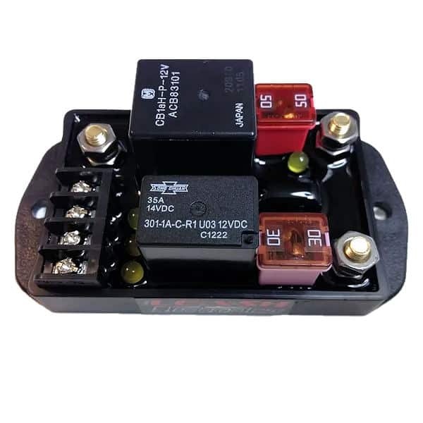
Leash Single Stage Nitrous Relay Board with Transbrake ... Wiring your nitrous kit has NEVER been so easy or fast!! Simply connect your battery + and - to the board, connect the 12 volt power from your throttle switch, connect the transbrake or clutch 12 volt signal for nitrous safety so that your nitrous will not come on when you're on the transbrake.
Nos Relay Wiring Diagram For Your Needs Nos Relay Wiring Diagram from tse1.mm.bing.net Print the electrical wiring diagram off and use highlighters to be able to trace the routine. When you make use of your finger or even the actual circuit with your eyes, it is easy to mistrace the circuit. One trick that I actually 2 to print out the same wiring plan off twice.
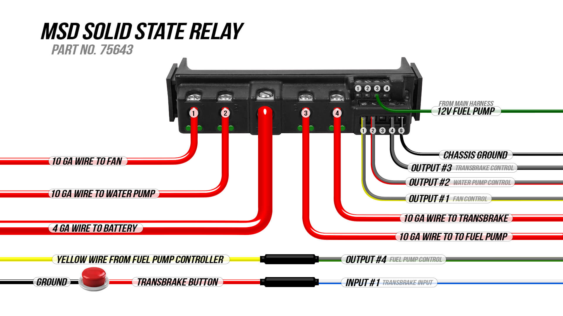
NOS 15620NOS NOS Solid State Relay - Holley NOS Aluminum Adjustable Wrench $73.30 Part# 16135NOS Wiring Tools $10.94 - $390.95 16 Products NOS have addressed the need for a reliable, rugged and affordable relay for controlling various electrical equipment on a race car.
betsson263-registrieren.de › 4-terminal-solenoid-diagram[email protected] - betsson263-registrieren.de email protected]
Wiring Diagram: MSD Solid State Relay - Holley Wiring Diagram: MSD Solid State Relay. By: Ray 04/20/2020. Here is how I wired the solid state relay into Terminator X. Back to Ride.
auto1x1.de › 4-terminal-solenoid-diagramauto1x1.de 4 terminal solenoid diagram. email protected]
Nitrous Express Wiring Diagram - schematron.org Wiring Diagrams. Nitrous Wiring Harness - This harness is specific for LS1 engines with a 4L60e Transmission and a Drive By Cable Throttle Body. This harness is Plug and Play with the engine and transmission, and only requires a 4 wire hook up to fire up the engine!
Nitrous Outlet's Pro Wiring Harness And ProMax Nitrous ... Nitrous Outlet has two different versions of the Pro Wiring Harness: one can be used with its WinMax Window Switch, and the other with the ProMax Progressive Controller. The harness allows for the WinMax and ProMax to be mounted in the glovebox or the console of the vehicle. A nitrous system can have a lot of accessories in use depending on the ...
Nitrous Oxide Instructions for kits & wiring You will also find wiring diagrams. coming soon, we will have awesome step by step color photo install instructions outlining almost every single step from taking your kit out of the box to putting on the finishing touches with easy to understand pictures. Our goal is to making installing your nitrous oxide kit easy and fun!! ALL NEW!!!
Engine Relay Wiring Diagram - Wiring Diagram Line Understanding automotive relays installing engine relay a heater motor and wiring diagram culture biker garage 4 pole starter solenoid for phase failure new facebook how to wire nissan er doesn t work ricks free auto repair advice tips more ac questions electrical tech first generation monte carlo club part 1 1990 1993 2 5l dodge dakota 10 ...
Nitrous Relay Wiring Diagram Also, stick to Hondata's wiring diagram. DO NOT look up relay wiring diagrams on the. OBD1 Honda ECU Nitrous Setup Guide for Hondata S and Neptune Print along with the wiring diagram for the nitrous output and relay. Follow the wiring diagram in Figure "C" if no relay is being. used, follow the diagram in Figure "D" if a relay and.
Wiring Diagrams - FuelTech USA Wiring Diagrams FT450 Honda K20-24Version: 1.0 | Size: 0.92 MB FT550 8 Cyl Smart CoilVersion: 1.0 | Size: 0.52 MB FT550 6 Cyl Smart CoilVersion: 1.0 | Size: 0.51 MB ...
Nitrous And Transbrake Wiring Diagram Wiring your nitrous kit has NEVER been so easy! connect you 12volt power from your throttle switch or manual nitrous button, connect you transbrake or clutch 12volt signal for nitrous safety so that Check out the wiring diagram in the pics. The stud labeled "2" is for the transbrake. It is activated by applying +12volts.
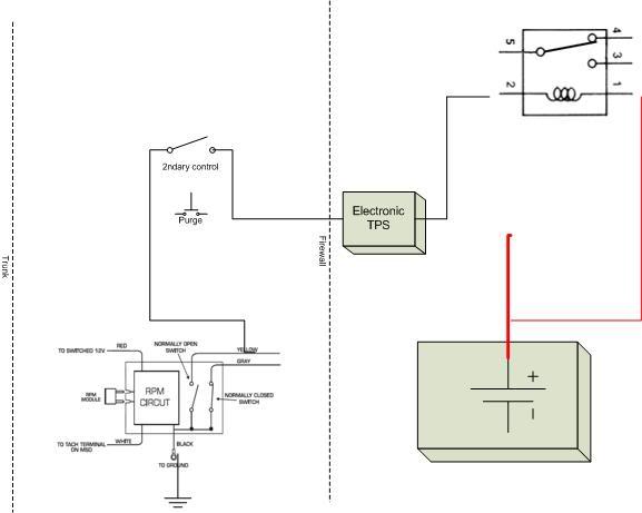

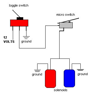
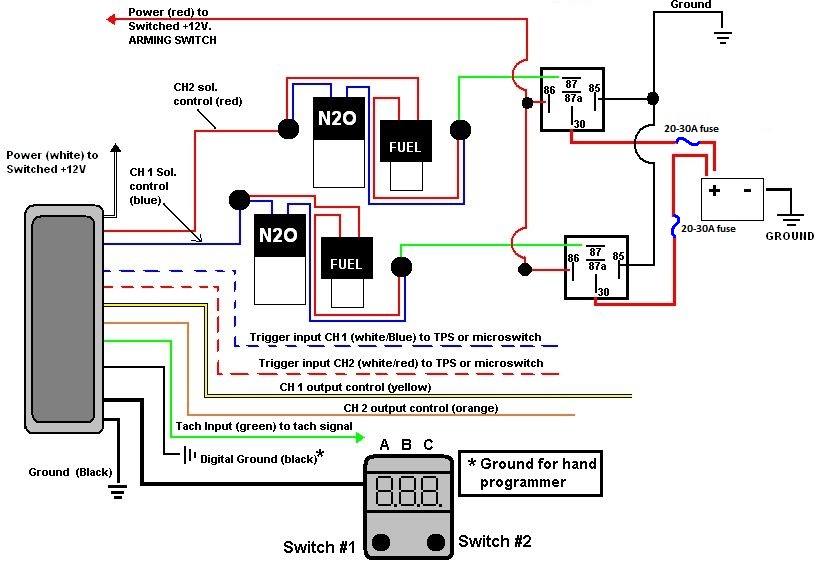







0 Response to "36 nos relay wiring diagram"
Post a Comment