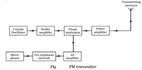
35 fm transmitter block diagram
The link: http://www.laughingpoliceman.com/jammers.htm The text: We, at the LPWS have often been accused of being jammers, but this is far from the truth. Admittedly, there is the playing of music on repeaters, but these are usually idle until one of our members comes along with a jolly tune (see the selection for download!). An analogy of what occurs could be the following:- You stand on a river bridge calmly throwing stones into the water, a few anglers a mile or so away hear this a... >A spectrum analyser is not what you need, because it only shows the energy of single channels, over the whole spectrum. However it wont show a spread spectrum signal using direct sequencing or frequency hopping. Try to measure the curents induced in your body instead. This will cover all available technologies. Because it measures the effect, not the method used to cause it. Ths is necessary because several technologies are available to cause the effects we see. It can be microwaves, or lase...
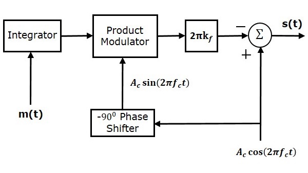
Fig. 1 shows the simplified block diagram of the PLL based FM audio transmitter. The PLL sets the carrier frequency, and the modulation is applied directly at ...
Fm transmitter block diagram
Mar 28, 2012 · The circuit can also be used as a remote control transmitter. FM Demodulator using PLL – This is a good circuit of an FM demodulator with a schematic diagram, a design of FM demodulator, and working of PLL with block diagram. This will definitely be useful for your educational purposes. FM stereo demodulator using AN7415 – Stereo ... Direct FM. Indirect FM. See notes for diagrams ... FM Transmitters/Receiver – Key Components (review) ... Two blocks: Mixer and Modulator.18 pages I am building a FM broadcast band transmitter. Don't worry, it will be operated in the FCC unlicensed allowance, but I am doing this as a senior project for college. I have finished my block diagram and I am now building each section. In lab at school whenever we made a FM signal, for the most part, we just used two function generators, or an IC. I want to building this entire thing without using digital circuits and only a few ICs. What is the best way to frequency modulate a baseband s...
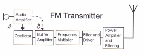
Fm transmitter block diagram. May 13, 2021 · Block diagram of a low level FM broadcast transmitter is shown in figure. The master oscillator generates the RF signal (carrier) required for modulation. Master oscillator is generally a well defined LC oscillator. The buffer amplifier is used to make the oscillator frequency free from the loading of the next stages. FM transmitter is the whole unit, which takes the audio signal as an input and delivers FM wave to the antenna as an output to be transmitted. The block diagram ... Apr 14, 2015 · Block diagram of FM transmitter and receiver and its explanation. FM transmitter. Frequency Modulation is the process in which the frequency of the carrier signal is ... FM Modulation System and FM modulators and transmitters i.e reactance modulator, frequency multiplier, FM transmitter block diagram.
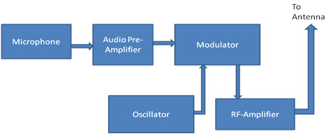
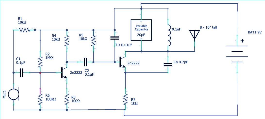
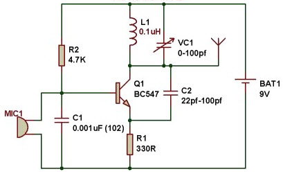
Block Diagram of FM Transmitter Working of FM Transmitter Circuit. The following circuit diagram shows the FM transmitter circuit and the required electrical and electronic components for this circuit is the power supply of 9V, resistor, capacitor, trimmer capacitor, inductor, mic, transmitter, and antenna. Let us consider the microphone to understand the sound signals and inside the mic, there is a presence of the capacitive sensor. Block Diagram Of Fm Transmitter e-Book Name : Block Diagram Of Fm Transmitter - Read Block Diagram Of Fm Transmitter PDF on your Android, iPhone, iPad or PC directly, the following PDF file is submitted in 1 Jul, 2020, Ebook ID PDF-8BDOFT12. Download full version PDF for Block Diagram Of Fm Transmitter using the link below: € Download: BLOCK ... F.M. Transmitter Tutorial - Block Diagrams - Electronics Circuit and Tutorials - Hobby Science Projects - The microphone converts sound pressure wave to ... This weekend is our stake conference. We were looking forward to going to the adult session this evening, but an hour before the meeting my wife notifies me she isn't feeling well. Over the next hour this is my thought process and what went down: * We live on the same block as the stake center. * I was stake technology clerk for 15+ years and am well familiar with the building's systems. * I'm also an [extra class amateur radio licensee](https://hamstudy.org/content/how) (ham operator, big time...
FM Transmitter Working Principle. The main function of an FM Transmitter Circuit is to transmit the sound using radio waves. So, at first, an FM Transmitter Circuit converts the sound or audio into radio wave then it transmit. You can see, in the block diagram of the FM Transmitter, the first block is the Microphone. Can anyone please provide me a block diagram for spectrum sensing, preferably matched filter detection? I am working on spectrum sensing in cognitive radio. My aim is to detect the presence of primary user which is going to be an FM transmitter. I am using RTL-SDR for receiving the signal. Update: Here's a reference block diagram I cam across from a technical paper https://www.researchgate.net/profile/Eduardo_Avendano_fernandez/publication/295932476/figure/fig3/AS:333565486223362@1456539617543/... "A spectrum analyser is not what you need, because it only shows the energy of single channels, over the whole spectrum. However it wont show a spread spectrum signal using direct sequencing or frequency hopping. Try to measure the curents induced in your body instead. This will cover all available technologies for directed energy weapons. Because it measures the effect, not the method used to cause it. Ths is necessary because several technologies are available to cause the effects we see. It ... I am building a FM broadcast band transmitter. Don't worry, it will be operated in the FCC unlicensed allowance, but I am doing this as a senior project for college. I have finished my block diagram and I am now building each section. In lab at school whenever we made a FM signal, for the most part, we just used two function generators, or an IC. I want to building this entire thing without using digital circuits and only a few ICs. What is the best way to frequency modulate a baseband s...
Fm Transmitter Circuit Working And Its Applications
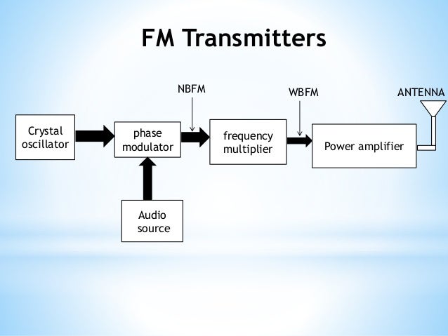
Direct FM. Indirect FM. See notes for diagrams ... FM Transmitters/Receiver – Key Components (review) ... Two blocks: Mixer and Modulator.18 pages
Analog Communication Fm Modulators
Mar 28, 2012 · The circuit can also be used as a remote control transmitter. FM Demodulator using PLL – This is a good circuit of an FM demodulator with a schematic diagram, a design of FM demodulator, and working of PLL with block diagram. This will definitely be useful for your educational purposes. FM stereo demodulator using AN7415 – Stereo ...
Frequency Modulation Fm Ni

Fm Transmitter Block Diagram With Explanation Electronics And Communication Study Materials
How To Build Fm Transmitter Circuit Soldering Mind
Block Diagram Of Fm Transmitter Download Scientific Diagram

Stereophonic Fm Transmission Circuit Design

Pll Based Fm Audio Transmitter Block Diagram Download Scientific Diagram
Brats Advanced Amateur Radio Tuition Course
1 5 Watt Fm Transmitter Tags Circuit Schematic Diagram
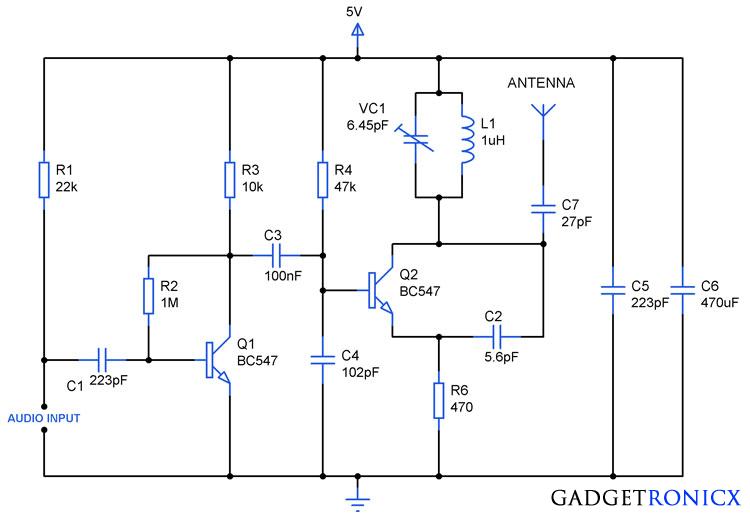
Fm Transmitter Circuit Using Transistors Gadgetronicx

Block Diagram Of Fm Dcsk Uwb Transmitter A And Receiver B Download Scientific Diagram
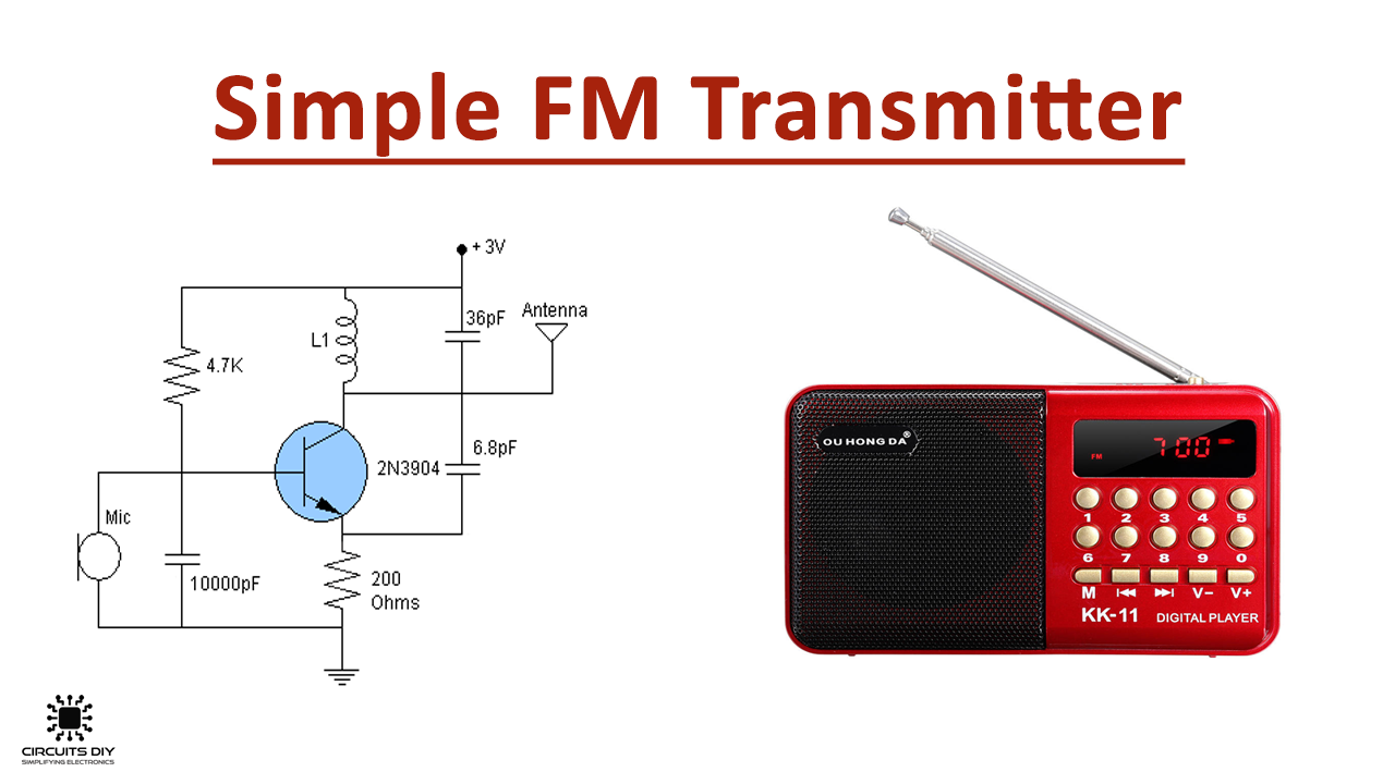
Simple Fm Transmitter Circuit Using 2n3904 Transistor

Pll Based Fm Audio Transmitter Block Diagram Download Scientific Diagram

4 Watt Fm Transmitter
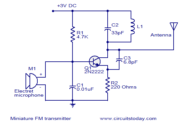
Miniature Fm Transmitterelectronics Project Circuts
1

Transmitter Vs Receiver Transmitter Types Receiver Types Difference

Fm Microwave Radio Transmitter Block Diagram Microwave Radio Transmitter Block Diagram A Block Diagram Description Of
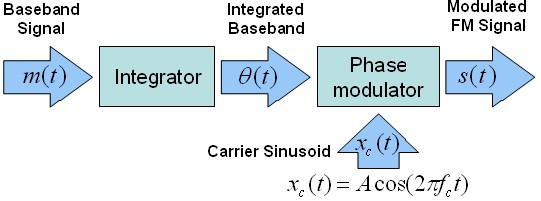
Phase Modulation
Radio Transmission Am Fm Transmitter And Af Rf Section
Fm Transmitter Circuit For Broadcasting Full Diy Project

Draw The Block Diagram Of An Fm Receiver And Explain Its Working Sarthaks Econnect Largest Online Education Community

Arduino Fm Transmitter Engineering Projects

1 5v Wireless Fm Transmitter Circuit Circuit Diagram
Brats Advanced Amateur Radio Tuition Course
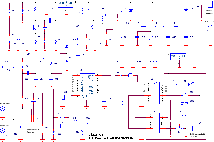
5w Pll Fm Transmitter

Simple Fm Transmitter Circuit Using Transistor

Electrical And Electronics Engineering Fm Transmitter Block Diagram
1201773 Universal Fm Transmitter Block Diagram Block Iti Hong Kong
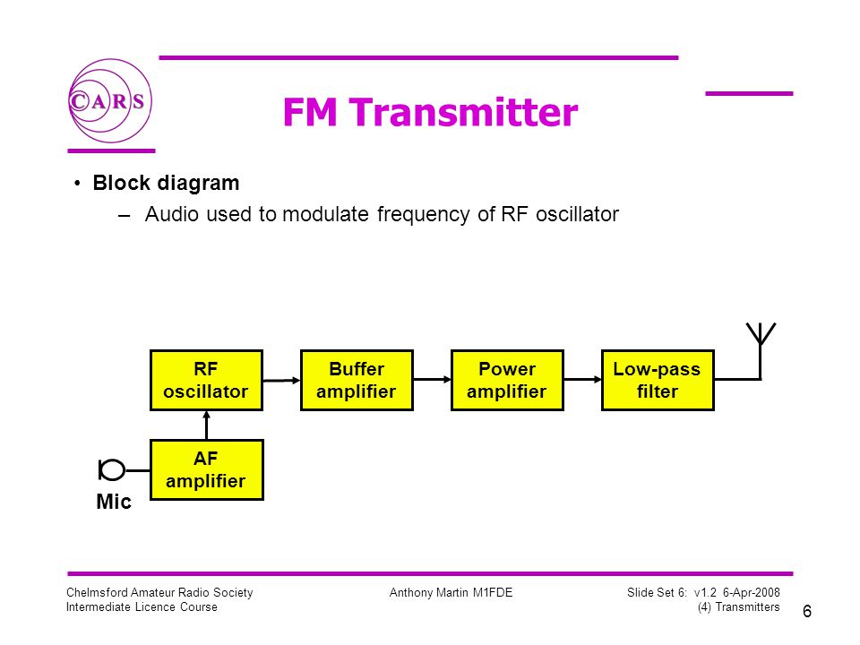
Chelmsford Amateur Radio Society Intermediate Course 4 Transmitters Ppt Video Online Download
Fm Transmitter And Receivers

High Power Fm Transmitter Project Diy
Fm Transmitter Circuit Working And Its Applications

9v Fm Transmitter Circuit Diagram
0 Response to "35 fm transmitter block diagram"
Post a Comment