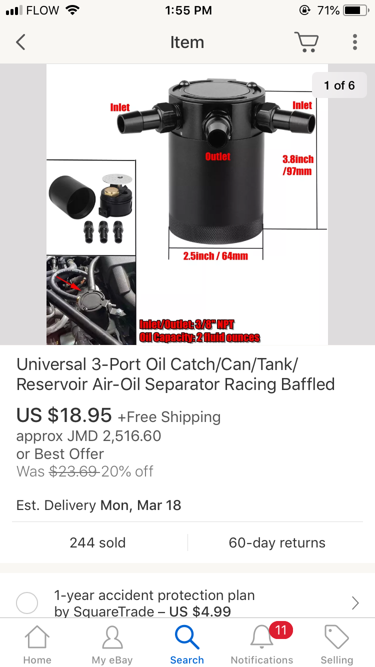
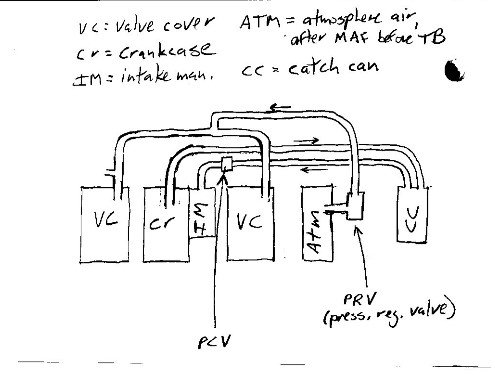
38 oil catch tank installation diagram
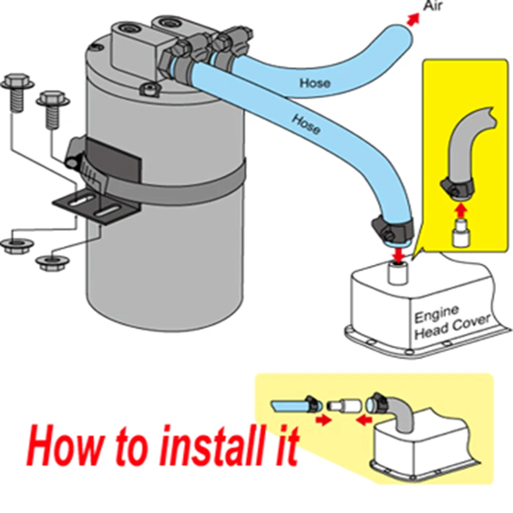
Install tank as close as possible to the pump pressure switch to reduce friction loss and elevation difference between the tank, water supply main, and switch. 3. After installation, be sure the pressure switch is set low enough to shut the pump off. If all valves are closed and the pressure switch With an oil catch can, you effectively separate the air from the oil. This filter sends the air back to the engine without the oil so it can continue feeding the vehicle. The oil catch tank gets fitted to the crankcase's breather system. You place it between the intake system and the breather outlet.
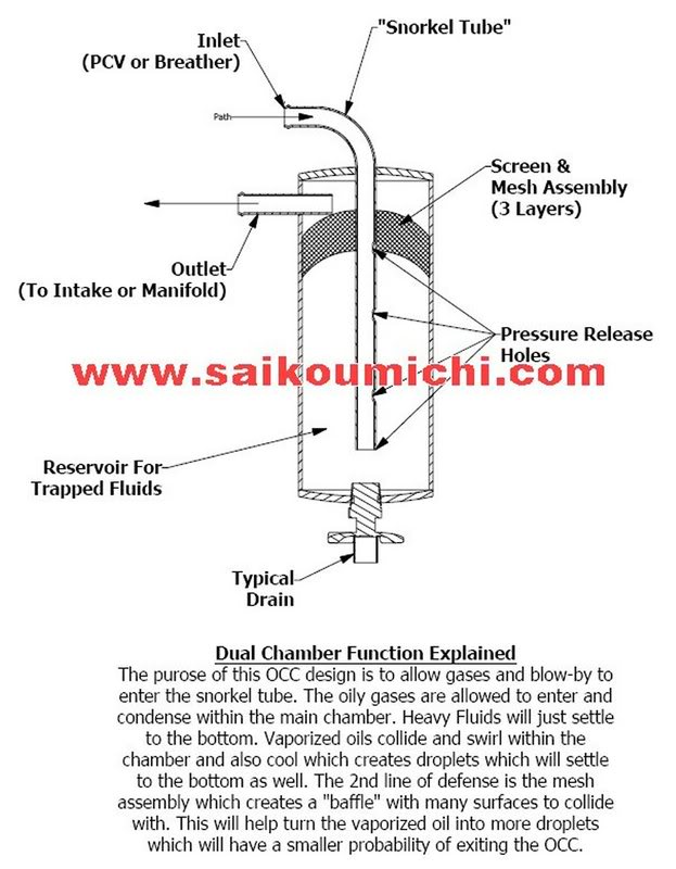
The whole idea behind the catch can is to catch the vapour, remove the oil and return cleaner vapour into the TIP (when venting back to TIP), or vent to atmosphere for an even cleaner system. A catch can with baffles works more efficiently at seperating the oil from the vapour but if you're unable to get one with baffles you can use wire brillo ...

Oil catch tank installation diagram
McNally Oil Catch Can Kits are a true oil PCV crankcase evacuation and separation system that is engineered to eliminate valve coking issues, increase fuel economy by eliminating oil associated detonation, reduce tail pipe emissions, and prolong engine life by removing damaging combustion by-products and trapping them from ingestion via the intake air charge. All about Subaru's Original Air/Oil Separator & Why You Need One. The Crawford Performance Air Oil Separator (AOS) is the original solution to Subaru's notorious oiling system issues. Although the technology was pre-existing with other vehicle brands such as Porsche, Crawford Performance is the inventor of the first system specifically for Subaru. The oil catch can OCC)( is a device designed to trap these oil droplets, allowing the air to escape from the crankcase with the lowest content of oil as possible and thus reducing the generation , and emission of extra pollutants during the combustion of the air-fuel mixture.
Oil catch tank installation diagram. ARE New Atmospheric Vent Can -- Patented Design. Introducing our NEWEST all unique design "Atmospheric Vent Can" (patent pending). Absolutely the most efficient and compact design which allows the highest mounting point possible by incorporating the dry sump tank vent to astmosphere at the higest point of the canister. What does a catch can do and how do you install one? The boys from MCM are here to show you how its done! Mad New MCM Keytags available now: http://mightycar... Installing the HPD Catch Can: Part One. Installing the HPD Catch Can: Part Two. This is a guide for installing the HPD catch can into the engine bay of a NW Pajero. It should the same for most of the Pajero models. Its broken into three parts the first is just a quick run down on the HPD catch can, then the next two are the actual fitting guide. Gen 2 Oil Catch Can by McNally Gen 2 CC written installation instructions Gen 2 CC written installation diagram Gen 2 CC written installation diagram for FORD 1.6L - 2.0L -2.3L PFDI Engines Gen 2 CC written installation diagram for FORD 3.5L - 2.7L GTDI Engines Gen 2 CC written installation diagram for FORD 5.0L - 7.3L PFDI Engines
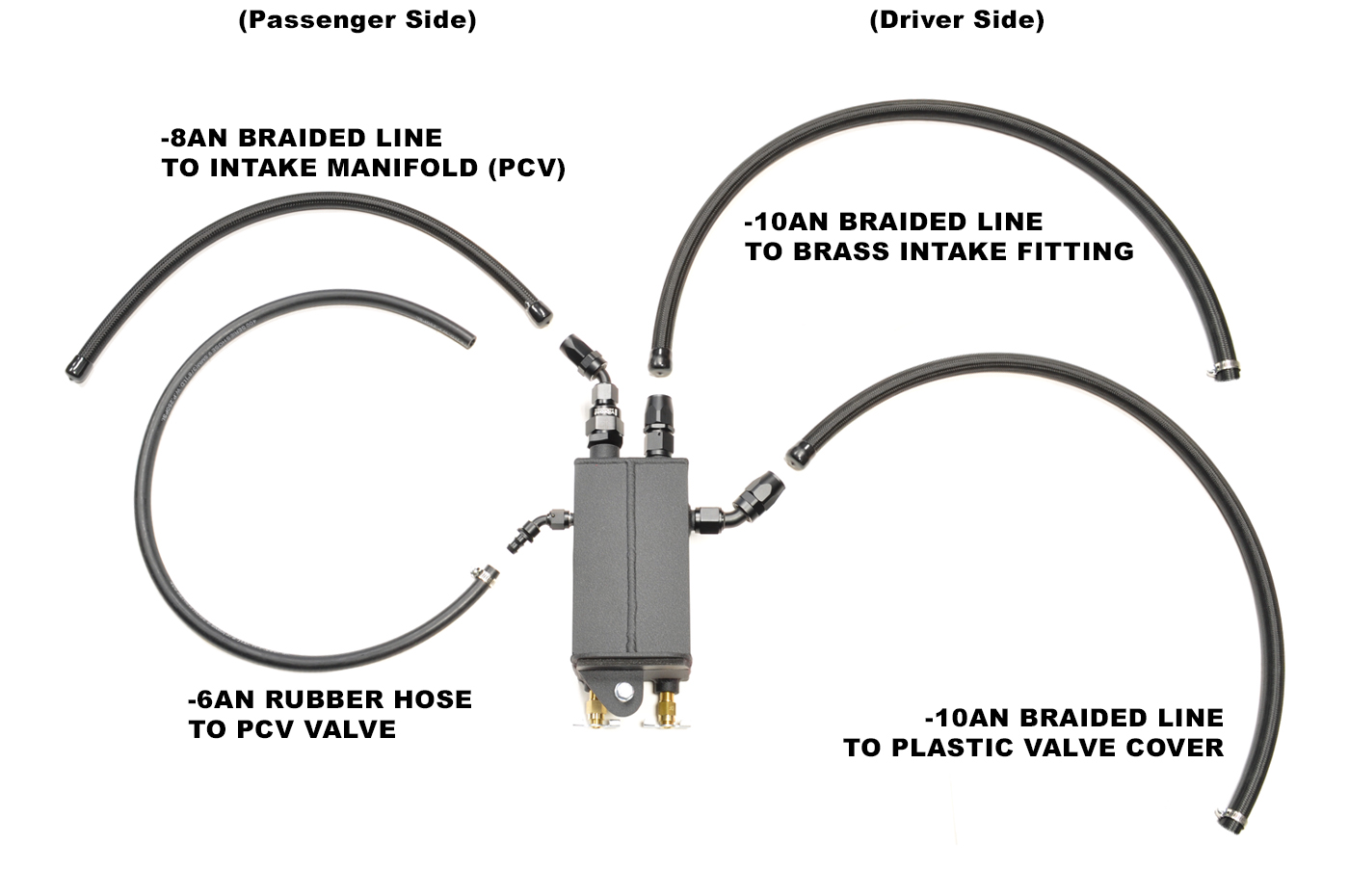
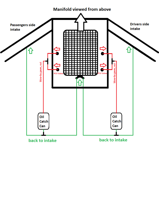
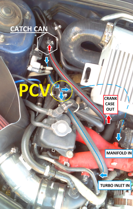
RX Catch Can installation& PCV system The LS based motors have a PCV system that at best is pretty ineffective. This allows oil mist to enter the intake manifold causing undue carbon buildup on the piston tops & valve surfaces & detonation from the contaminated air charge. The catch can goes Oil catch cans and breather tanks look similar and do similar jobs, but they serve different purposes. Oil Catch Cans Normally, the PCV (positive crankcase ventilation) valve uses intake vacuum to relieve the pressure inside your crankcase, but that can result in oil mist and other blow-by contaminants building up on the valve and pistons, especially in direct-injection engines. An oil catch can typically uses a baffle system that removes the oil from the air-oil mixture. The oil falls to the bottom of the can where it is stored until the can is emptied. An oil catch can doesn't add any power or make any cool noises so it is often overlooked when modifying vehicles. FBM S2000 8.8 Rear Installation Instructions. FBM S2000 H11 Head Stud Installation Instructions. FBM S2000 V160 Hardware Installation Instructions. FBM Supra V160 Installation Instructions. S2000 Dual Pump Wiring Diagram Installation Instructions. S2000 Stage 1 Installation Instructions. S2000 Surge Tank Diagram Installation Instructions.
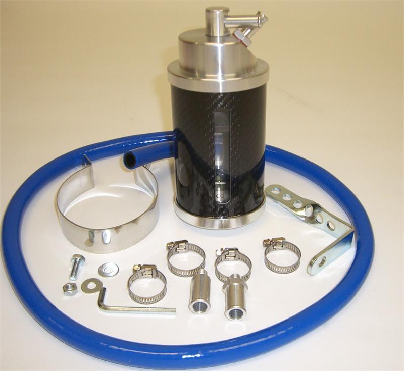
Oil Catch Tank Installation Guide. Click on each page to view large version, PDF format can be downloaded here: DOWNLOAD (PDF 324kb) 4.8. Install a 1/2" JIC double male coupler in one end of the 18" hydraulic line in the test kit. Install a 90 deg. 1/2" JIC double male elbow in the other end. See Figure 4.8. 4.9. Position a catch pan beneath the hydro motor. Have the hydraulic pressure and flow test kit and two 1/2" JIC plugs within reach. Our direct fit oil catch can kits feature specific brackets and hoses for an easy bolt-in installation. These catch cans are fully serviceable, so you can clean them yourself. It is important to filter oil particles from the PCV/CCV systems and protect your intake from harmful blow-by. A catch tank serves to collect expelled coolant to be drained from that tank at a later point. While both a recovery/reservoir tank and a catch tank hold excess coolant, a recovery/reservoir will automatically put the coolant back in the system, where as a catch tank will hold the coolant until it can be emptied.
A breather attaches to the top of the catch can and is secured with a clamp. Remember, an oil separator does not have a breather and will be part of the closed PCV system. Any vehicle with a PCV can benefit from an oil separator since the oil vapors will always find their way into the intake.
This manual provides how to install racing kit parts for the 2007 Ninja ZX-6R and how to tune up basically. As for the basic knowledge, refer to the base Service Manual for the Ninja ZX-6R (P/No.
Place a catch pan suitable for holding heating oil in it underneath the heating oil tank. The pan needs to be deep enough to hold any oil that may leak continuously during times when you are not around to check on it, for example, while you are away on holiday. Wherever you decide to install your tank, the floor must be level.
This Instructable will cover the steps to create an Oil Catch Can (Oil Tank Reservoir). Oil Catch Cans are devices that are installed in cars in order to avoid zoot, water and oil to recirculate to the engine. Typically, the valve cover has a breather and a hose that's directly connected to the intake. What this does is to burn off blow-by gases.

1301.4 Fuel Tanks, Piping and Valves. The tank, piping and valves for appliances burning oil shall be installed in accordance with the requirements of this chapter. Where an oil burner is served by a tank, any part of which is above the level of the burner inlet connection and where the fuel supply line is taken from the top of the tank, an ...
A catch can is a container that is plumbed into the car engine in a manor that will catch oil vapors. These cans are sometimes large and others times not so much. Some of them will have breathers on top, while others will be a closed system. No matter what, a good catch can will have some sort of aerator or separator located inside.
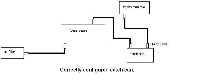
An oil catch tank (can) is fitted in line of the crank case breather system. It is placed in between the breather outlet and the intake system. As the crank vapors pass through the catch tank (can) the oil droplets, un-burnt fuel, and water vapor condense and settle in the tank. This stops them from reaching the intake and causing the issues ...
Use #200 oil stone for eliminating any stepped portions. Use #200 oil stone for smoothing and #300 oil stone for finishing. NOTE These procedures make air resistance less and intake/exhaust gas flow more smooth. However, much more effect can not be expected by excessive grinding and smoothing.
oil tanks, oil flow 1/2- related fo-92 ( sse) —o to catch basin 44. min »ter f.Æl stor t sse) flØØ o c sse) oil cay 550 ca-. ago c sse) fo-96 fo-sa c sse) ... flow diagram of fuel oil system c ssf diesel engines) esign pipe 9ec. 151. s 151.6 151.4 151. s 151.4 pipe sch. class 4 ffi date e 2

There are a few different designs when it comes to oil catch cans. Oil separators are included in this category and are used in line with the PCV system on v...
The captured oil is safely stored in the catch can until it can be properly disposed of during your next routine oil change. It's an inexpensive option to keep the engine in top shape, and it's never a bad idea to invest in a catch can. The diagram below illustrates the basics of how a catch can works. The purple arrow represents the air/oil ...
The oil catch can OCC)( is a device designed to trap these oil droplets, allowing the air to escape from the crankcase with the lowest content of oil as possible and thus reducing the generation , and emission of extra pollutants during the combustion of the air-fuel mixture.
All about Subaru's Original Air/Oil Separator & Why You Need One. The Crawford Performance Air Oil Separator (AOS) is the original solution to Subaru's notorious oiling system issues. Although the technology was pre-existing with other vehicle brands such as Porsche, Crawford Performance is the inventor of the first system specifically for Subaru.

McNally Oil Catch Can Kits are a true oil PCV crankcase evacuation and separation system that is engineered to eliminate valve coking issues, increase fuel economy by eliminating oil associated detonation, reduce tail pipe emissions, and prolong engine life by removing damaging combustion by-products and trapping them from ingestion via the intake air charge.


0 Response to "38 oil catch tank installation diagram"
Post a Comment