39 heat pump ts diagram
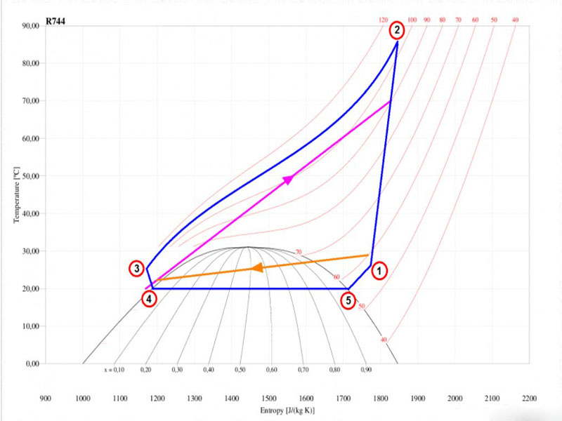
A temperature-entropy diagram, or T-s diagram, is a thermodynamic diagram used in thermodynamics to visualize changes to temperature and specific entropy during a thermodynamic process or cycle as the graph of a curve.It is a useful and common tool, particularly because it helps to visualize the heat transfer during a process. For reversible (ideal) processes, the area under the T-s ... CLIMATEMASTER WATER-SOURCE HEAT PUMPS Tranquility ® 20 (TS) Series Rev.: September 23, 2021 6 ClimateMaster Water-Source Heat Pumps Unit Physical Data Tranquility® 20 Single-Stage (TS) Series (60Hz) Model 006 009 012 018 024 030 036 042 048 060 070
Caution; water heat to improper pipes, pump is to Check the data to make Sure it With the suppty. HACR circu it and abu of the be nameplate for mini and/or An water screen strainer is recommended but it is poor water quality may to unit to the wiring diagram with the ONLY for and wiring be into unit through the holes on the unit's cabinet. protect

Heat pump ts diagram
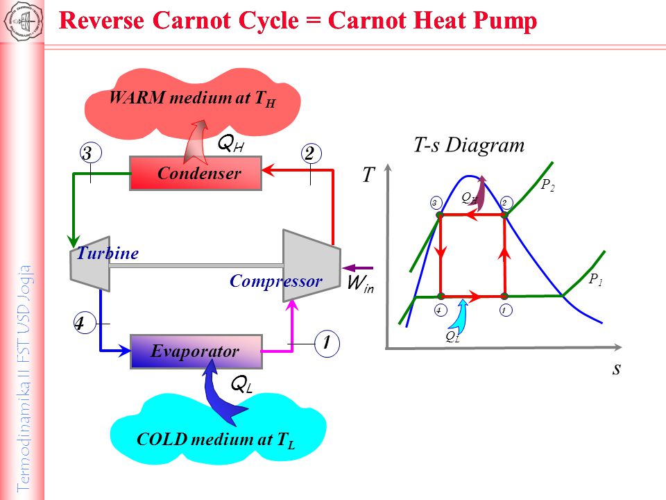
The TS Diagram shows us that the reheat rankine cycle combines all of the advantages of of the superheat method with the simple method of increasing the boiler pressure and decreasing the condenser pressure. The result is an increase in Q H and no change or even a decrease in Q C. Both of these effects result in a significant increase in the ... Ch 9, Lesson A, Page 5 - Net Work on a T-S Diagram. You probably recall from chapter 8 that the area under a process path on a TS Diagram is equal to the ratio of the heat transfer rate to the mass flow rate for internally reversible, steady-state, SISO processes. Thermodynamic heat pump cycles or refrigeration cycles are the conceptual and mathematical models for heat pump, air conditioning and refrigeration systems. A heat pump is a mechanical system that allows for the transmission of heat from one location (the "source") at a lower temperature to another location (the "sink" or "heat sink") at a higher temperature.
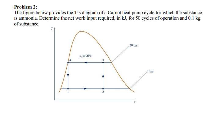
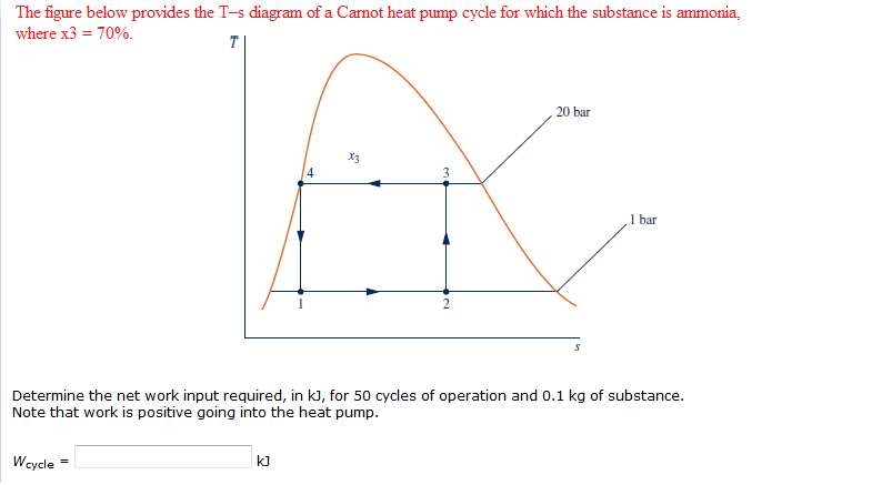
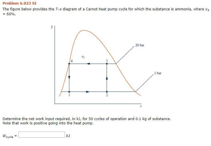
Heat pump ts diagram. The figure below provides the T-s diagram of a Carnot heat pump cycle for which the substance is ammonia. Determine the net work input required, in kJ, for 50 cycles of operation and 0.1 kg of substance. Question: The figure below provides the T-s diagram of a Carnot heat pump cycle for which the substance is ammonia. Determine the net work ... Pump (P) Boiler (B) Turbine (T) Condenser (C) Pump: Point 1-2 indicates pump in Rankine cycle; Work done incurs to the system. Pressure is increased in this stage. Boiler: Point 2-3 represents the boiler in the cycle. Heat is added to the high pressured fluid by the boiler. Temperature is increased up to a boiling point. Download scientific diagram | T-s diagram for heat pump cycle. from publication: Thermodynamic Analysis on Hybrid Turbo Expander - Heat Pump System for Natural Gas Pressure Regulation | In natural ... T-s diagram is a useful and common tool, particularly because it helps to visualize the heat transfer during a process. An isentropic process is depicted as a vertical line on a T-s diagram, whereas an isothermal process is a horizontal line. In an idealized state, compression is a pump, compression in a compressor and expansion in a turbine are isentropic processes.
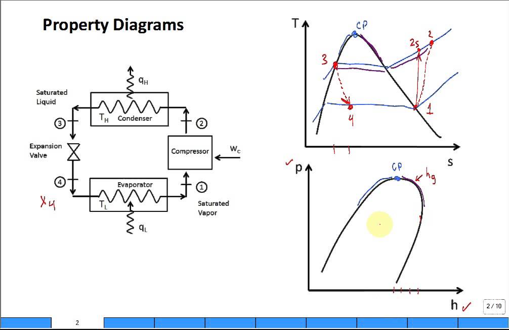
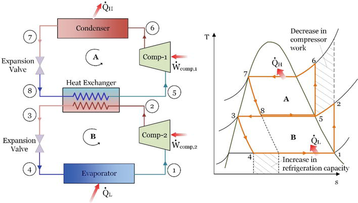
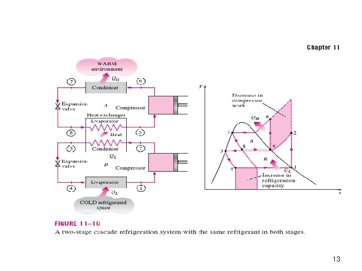
Figure 3 shows the different processes involved in the thermodynamic cycle of the heat pump, including the TS and ph diagrams. Measurements After the heat pump has been in function for about 10 minutes, and the pressures and temperatures appear to have stabilized, you can start measuring. You can measure either provides the heat input to the evaporator of a high-temperature cycle, e.g., 2 units in series • Normally a different refrigerant would be used in each separate cycle, in order to match the desired ranges of T & P. • The Ts diagram shows an ideal double-cascade system using the same refrigerant in each loop. † Some Heat Pump systems have a wire for AUX electric heat (usually W2), and also a separate wire for Emergency electric heat (usually E). This thermostat uses the W2 terminal for both AUX and Emergency Heat. Tape off your "E" wire, and confirm that all components function without it. Electrical requirem en ts ca b f ou d h rating plate located ... Even-Heat Control Diagram 17 Contact Infomation 18. LOCATION UOF HEAT P MP ... The heat pump gets its heat from the surrounding air; therefore, recirculation of the cold air off the top of the unit should be avoided. Enclosed spaces such as garages and sheds without
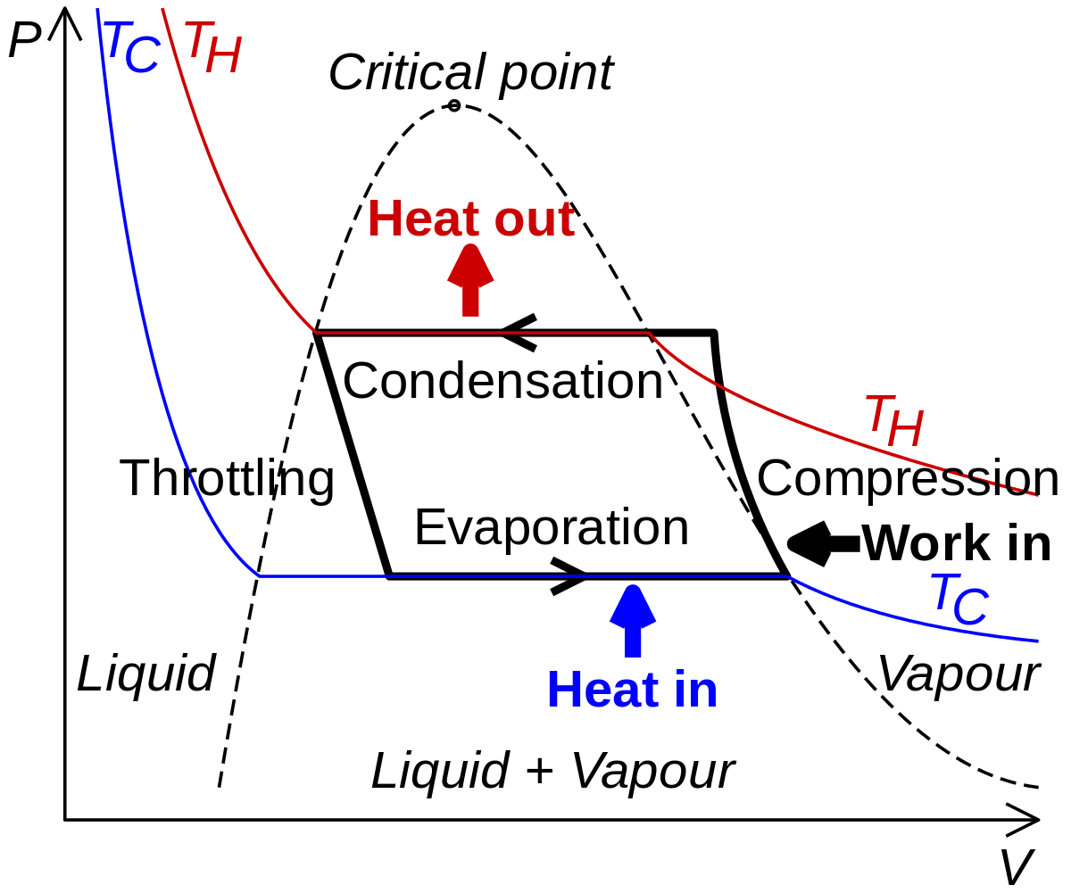
Download scientific diagram | The T-S diagram of a theoretical heat pump cycle for: (a) Zeotropic mixture, and (b) Pure refrigerant from publication: Assessment of refrigerant mixtures performance ... By the definition of entropy, the heat transferred to or from a system equals the area under the T-s curve of the process. Figure 13 is the T-s diagram for pure water. A T-s diagram can be constructed for any pure substance. It exhibits the same features as P-u diagrams. Temperature Entropy (T-s) Diagram Relationship, PV diagram, TS diagram, Change in Internal Energy, Change in Entropy, Work done, Heat Transferred, Constant Pressure Process, PVT Relationship, PV diagram, TS diagram, Change in Internal Energy, Change in Entropy, Work done, Heat Transferred, Constant Volume The direction of the cyclic process in theT-s diagram determines w hether this is a heat pump cycle (refrigeration cycle) or a work machine cycle (steam power cycle). Refrigeration cycles are anti-clockwise and the work represented by the green area is added to the cycle. Cyclic process of a simple compression refrigeration system Compressor power
Mechanical Engineering questions and answers. 20 bar The T-s diagram illustrates a Carnot heat pump cycle for which the substance is ammonia. Determine the net work input required, in kJ, for 50 cycles of operation and 0.1 kg of substance. 90 1 hur. Question: 20 bar The T-s diagram illustrates a Carnot heat pump cycle for which the substance is ...

T-S diagrams are ideal for reading heats in a closed cycle: Qh = positive area under curve (going from left to right) Qc = negative area under curve (going from right to left) So Qh - Qc per cycle = area within the closed curve, as you correctly state, and = W also. And e = 1 - (Qc/Qh). Nov 4, 2015. #5.

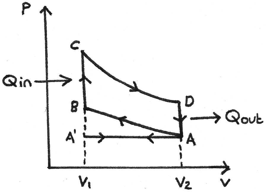
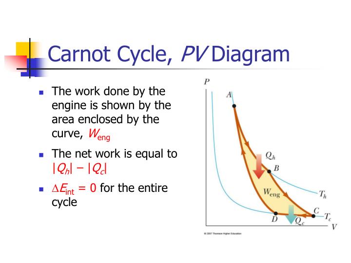
or heat pump cycles by controlling the process direction. On a pressure volume diagram or temperature entropy diagram, the clockwise and counterclockwise directions indicate power and heat pump cycles, respectively. Relationship to work Example of P-V diagram of a thermodynamic cycle. Because the net variation in state properties during a
NOTE: The remaining diagrams show single transformer installations for simplicity but all can ... (TS-2PE01). Power Extender Kit installation instructions for ... The heat pump lockout temperature can be used to force a switch from heat pump operation

Electrical Data - ECM Motor & Secondary Pump 58 TS Series Wiring Diagram Matrix 59 Typical Wiring Diagram - Single Phase TS Units with CXM Controller 60 Typical Wiring Diagram - Three Phase TS Units with DXM2 Controller 61 ... (TS) Series Water-Source Heat Pumps are designed to meet the challenges of today's HVAC demands with one of the ...

The schematic diagram of heat pump with discharge superheat (DSH) control is shown in Figure 1. The system used electronic expansion valve (EEV) to control discharge superheat (DSH) by using Pd and Td for refrigerant flow ... Suction superheat was calculated by Ts and Ps as equation (4)
Free shipping. Warranty: 10 years all parts.. Energy star.. AHRI certified..Made in USA! 2 stage option increases efficiency by up to 30%. Add on the 2 stage option, Get: Free 2 stage WIFI Thermostat & Quiet package.

FIG. 1 is a schematic diagram of a heat-pump water heater according to a first preferred embodiment of the present invention; FIG. 2 is a graph (T-H diagram) showing a relationship between temperature and enthalpy in a heat pump cycle using carbon dioxide as refrigerant, according to the first embodiment;

Miami Heat Pump offers a superior quality water source heating and air conditioning system. Designs for all applications, residential and commercial. Self contained packaged units and split systems information, manuals, and specifications.
Water Source Heat Pumps Vertical / Horizontal 1 - 5 Nominal Ton GEOCOOL SERIES Reader should pay particular attention to the words: NOTE, CAUTION, and WARNING. NOTES are intended to clarify or make the installation easier. CAUTIONS are given to prevent equipment damage.
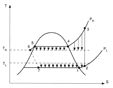
Hence the increase in heat rejection rate of VCRS compared to Carnot cycle is equal to the area 2''-2-2' (area A 1). This region is known as superheat horn, and is due to the replacement of isothermal heat rejection process of Carnot cycle by isobaric heat rejection in case of VCRS.
Thermodynamic heat pump cycles or refrigeration cycles are the conceptual and mathematical models for heat pump, air conditioning and refrigeration systems. A heat pump is a mechanical system that allows for the transmission of heat from one location (the "source") at a lower temperature to another location (the "sink" or "heat sink") at a higher temperature.
Ch 9, Lesson A, Page 5 - Net Work on a T-S Diagram. You probably recall from chapter 8 that the area under a process path on a TS Diagram is equal to the ratio of the heat transfer rate to the mass flow rate for internally reversible, steady-state, SISO processes.

The TS Diagram shows us that the reheat rankine cycle combines all of the advantages of of the superheat method with the simple method of increasing the boiler pressure and decreasing the condenser pressure. The result is an increase in Q H and no change or even a decrease in Q C. Both of these effects result in a significant increase in the ...


0 Response to "39 heat pump ts diagram"
Post a Comment