39 asco solenoid valve wiring diagram
WIRING DIAGRAM. FUNCTIONAL DIAGRAM. CLOSED. OPEN. 24 V DC. 0 V DC coil 1 coil 0 open valve closed valve function with latching coil. 50-60 Hanover Road, Florham Park, New Jersey 07932 www.ascovalve.com. ASCO Valves ... Wiring, Solenoid Temperature, Cause of Improper Operation.4 pages
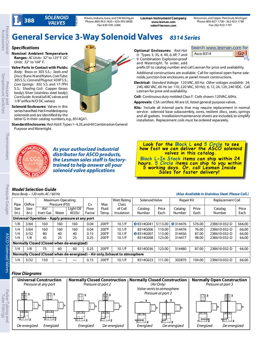
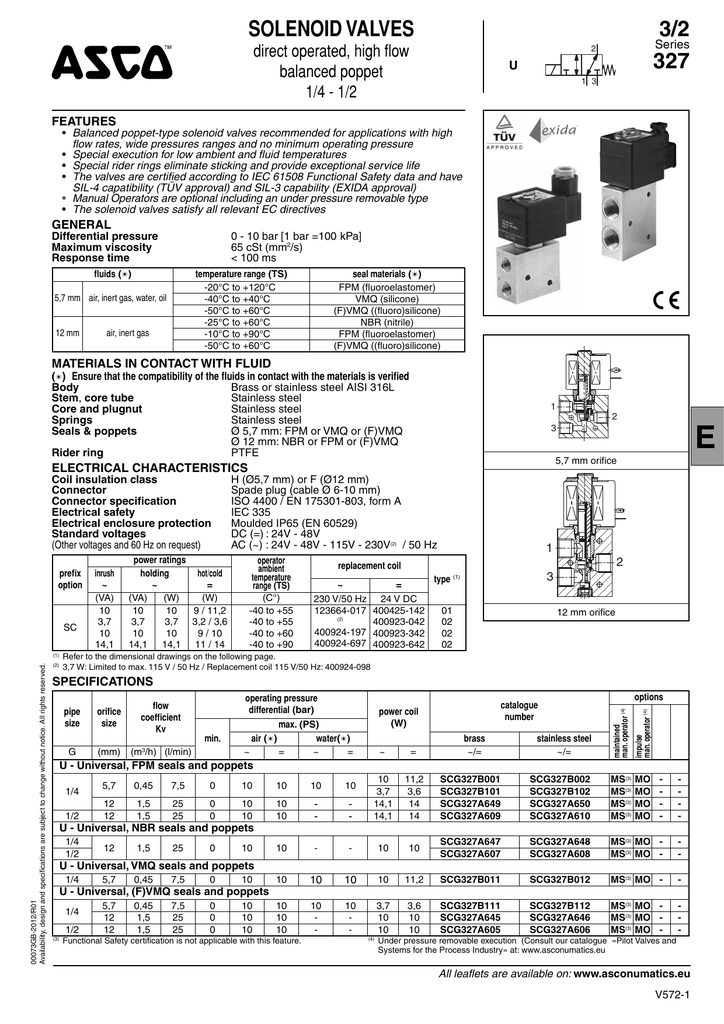
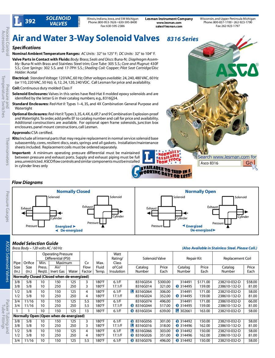
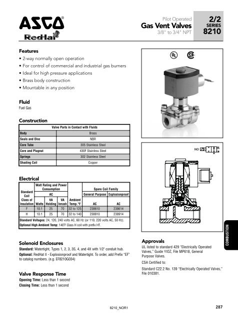
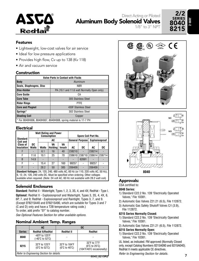
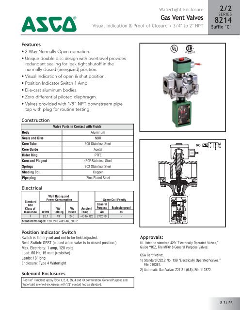
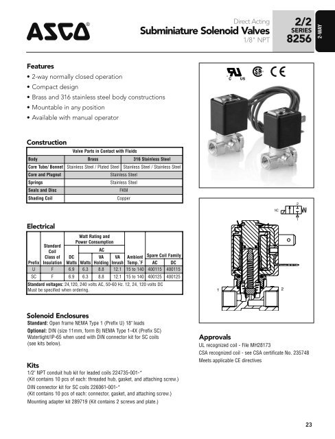
Two-way valves have one inlet and one outlet pipe connection. They are used to allow or shut off fluid flow, and are available in either: Normally Closed – ...26 pages

Asco solenoid valve wiring diagram
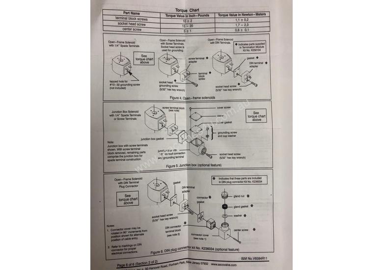
ASCO Valves. EASCO Valve, Inc.R 50 ... ASCOr solenoid valves with design change letter “G” or ... lead wires and 1/2I conduit connection is designed to meet.6 pages Asco Solenoid Valve 8262 Wiring Diagram. Quarter-turn manual operator with screw slot (suffix MS). Panel mount (prefix GP for conduit; consult ASCO for other electrical connections). Vacuum service. Aug 22, 2018 · 22.08.2018. 22.08.2018. 4 Comments. on Asco Redhat 2 Wiring Diagram. 4-Way/2 and 3 Position Valves. Four-ported Solenoid valves are supplied, as listed, with either RedHat II molded 4 and 5-Ported Valves Flow Diagrams. 2-W. A. Y. 1. 2-Way/2 Position Valves. Two-way solenoid valves have one inlet and one outlet, Solenoid valves are supplied, as listed, with either RedHat II.
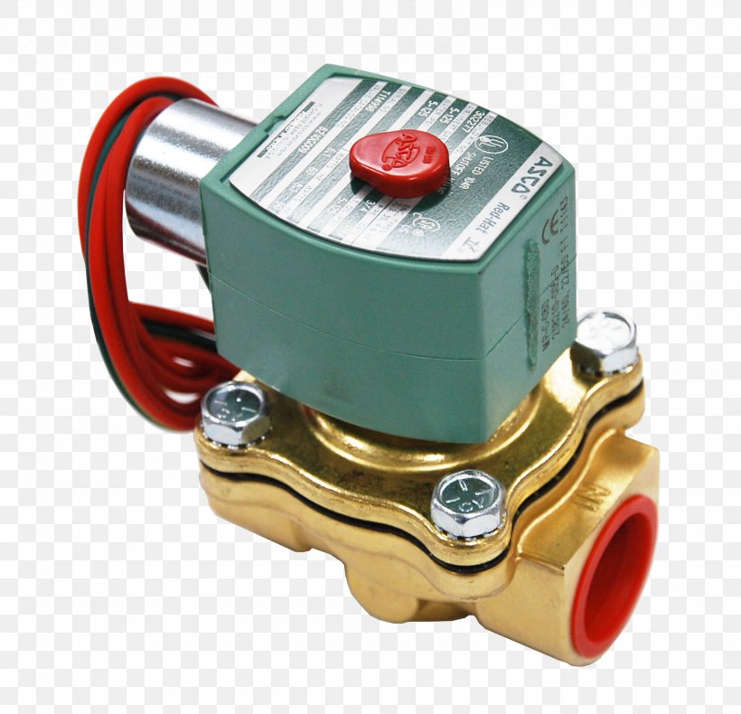
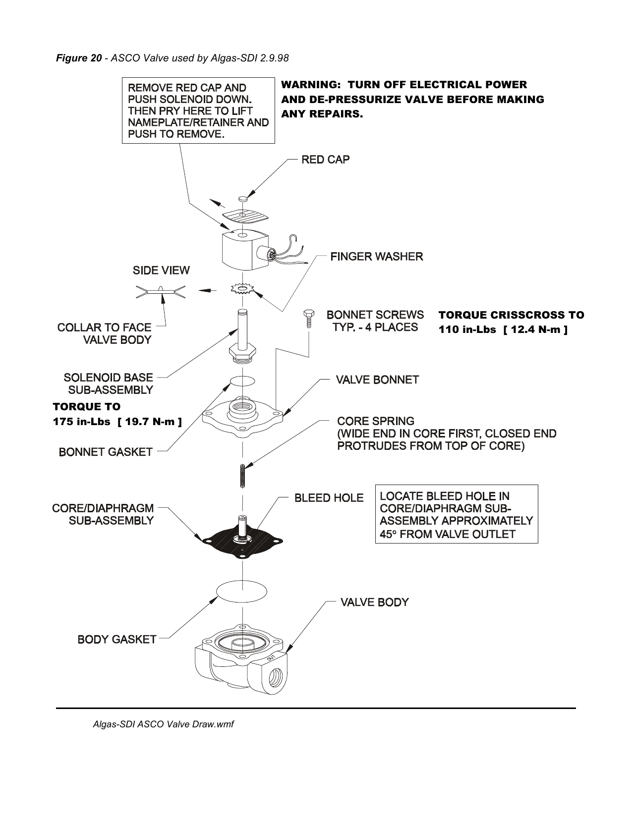
Asco solenoid valve wiring diagram. instructions for information on: Wiring, Solenoid Temperature,. Cause of Improper Operation, ... When Ordering Rebuild Kits for ASCO valves, order. Nov 06, 2017 · Asco 8210g034v 2 Way N O 1 Solenoid Valve 120 60 110 50 Vac. Asco Solenoid Valves Archives Heating And Process. 8210 V7294 R1 Asco Valve Net. Emerson Asco Ef8210g88 Solenoid Valve Specs. Wiring Diagram Asco 917 918 Remote Control Switch N O C Inc Accessories 14h 14ha 47 48 49 383880 Instruction Sheet Power Technologies. Jan 03, 2020 · asco solenoid valve wiring diagram free wiring diagram variety of asco solenoid valve wiring diagram a wiring diagram is a streamlined standard pictorial representation of an electric circuit it shows the parts of the circuit as simplified shapes and also the power as well as signal links in between the tools 4 engineering information solenoid valves asco asco valves have a solenoid mounted directly on the valve body the core is enclosed in a sealed tube providing a compact leaktight ... The green solenoid with lead wires and 1/2I conduit connection ... installed just as a solenoid and not attached to an ASCO valve, the core has.
on Asco Solenoid Valve 8262 Wiring Diagram. Series and valves are 2-way direct-acting general service below. To engage push type manual operator, push stem at base of valve body. HT or H. Avoid typical problems when installing a solenoid valve. Feb 24, 2018 · February 24, 2018 by headcontrolsystem. asco solenoid valve wiring diagram – Just What’s Wiring Diagram? A wiring diagram is a kind of schematic which utilizes abstract pictorial symbols to show all the interconnections of components in a system. Wiring diagrams are made up of two points: icons that stand for the parts in the circuit, as well as lines that represent the links in between them. Aug 22, 2018 · 22.08.2018. 22.08.2018. 4 Comments. on Asco Redhat 2 Wiring Diagram. 4-Way/2 and 3 Position Valves. Four-ported Solenoid valves are supplied, as listed, with either RedHat II molded 4 and 5-Ported Valves Flow Diagrams. 2-W. A. Y. 1. 2-Way/2 Position Valves. Two-way solenoid valves have one inlet and one outlet, Solenoid valves are supplied, as listed, with either RedHat II. Asco Solenoid Valve 8262 Wiring Diagram. Quarter-turn manual operator with screw slot (suffix MS). Panel mount (prefix GP for conduit; consult ASCO for other electrical connections). Vacuum service.
ASCO Valves. EASCO Valve, Inc.R 50 ... ASCOr solenoid valves with design change letter “G” or ... lead wires and 1/2I conduit connection is designed to meet.6 pages


0 Response to "39 asco solenoid valve wiring diagram"
Post a Comment