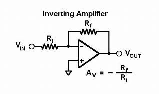
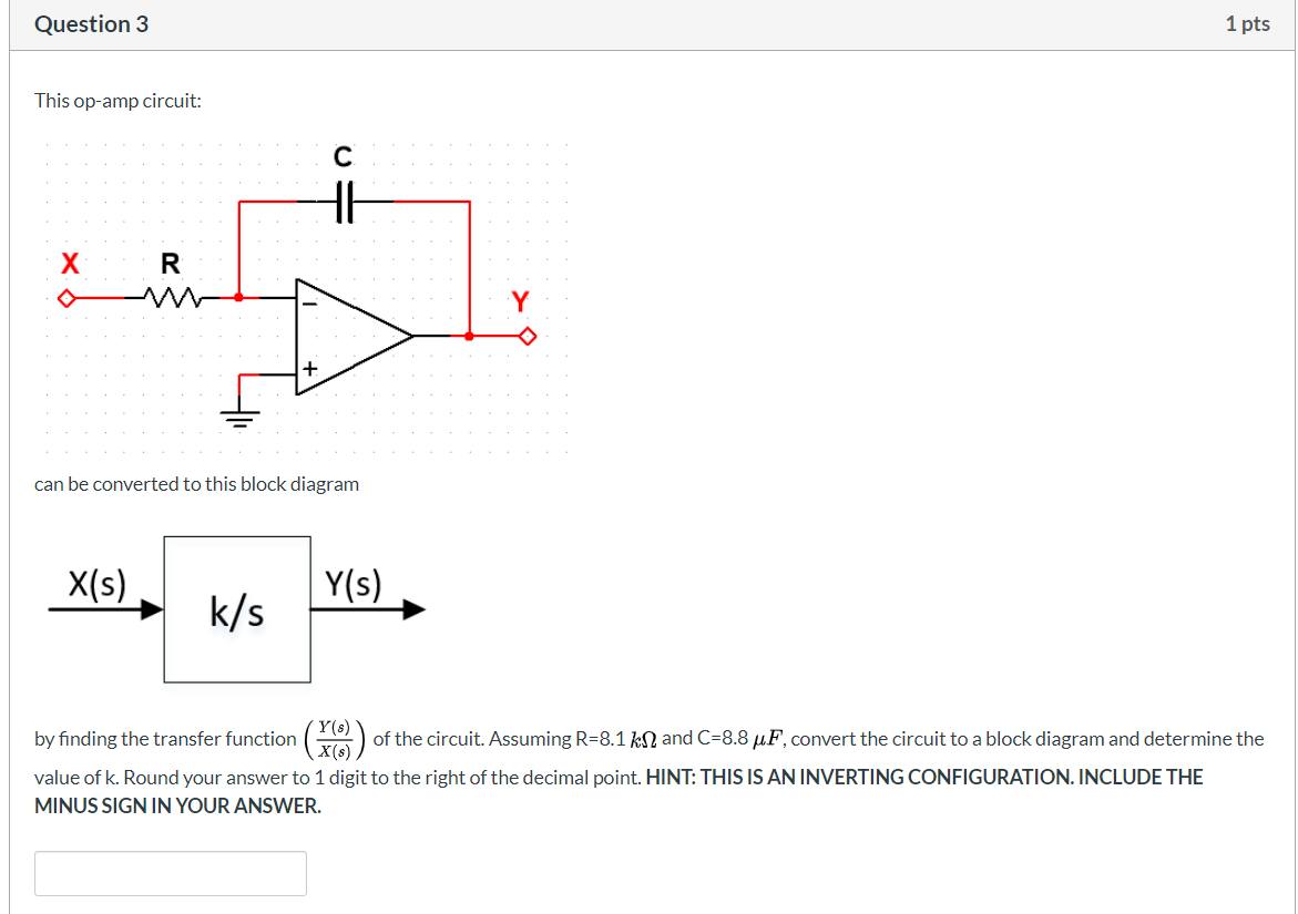
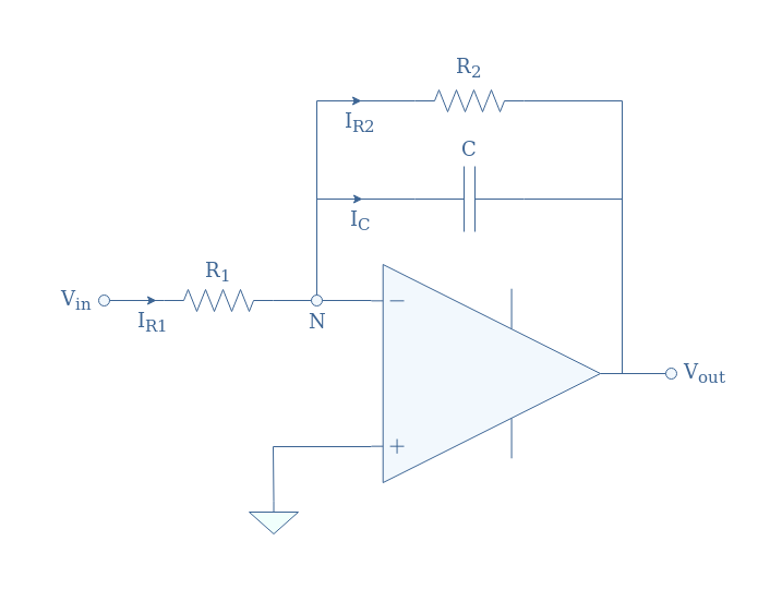
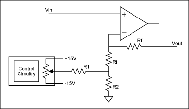
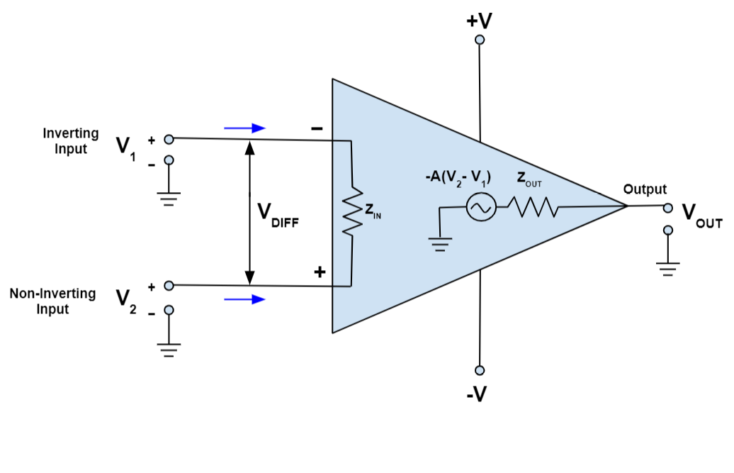
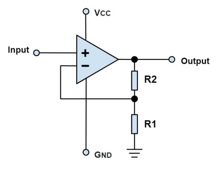
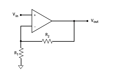
40 select the correct circuit diagram of the basic inverting amplifier configuration.
Solar Inverter Project Report - SlideShare 16/04/2016 · At the circuit this multivibrator is used to make power is too high, then we have to use the MOSFET IRFZ44. IRFZ44 provide high current to drive step-up transformer, so power is available in addition to the high voltage transformer. 36. 36 The power MOSFETs are connected in Push Pull configuration (Power amplifier). The MOSFETs will switch ... Solved Draw the circuit diagram of the basic inverting - Chegg Question: Draw the circuit diagram of the basic inverting amplifier configuration. Give an expression for the closed-loop voltage gain of the circuit in ...
Non-inverting Schmitt Trigger | Analog-integrated-circuits ... In non-inverting Schmitt trigger, the input signal is applied at the non-inverting terminal of op-amp as shown below. In this the voltage present at non-inverting terminal (V+) is compared with the voltage present at inverting terminal (V- = 0V) The operation of the circuit can be explained with the help of two conditions: 1.
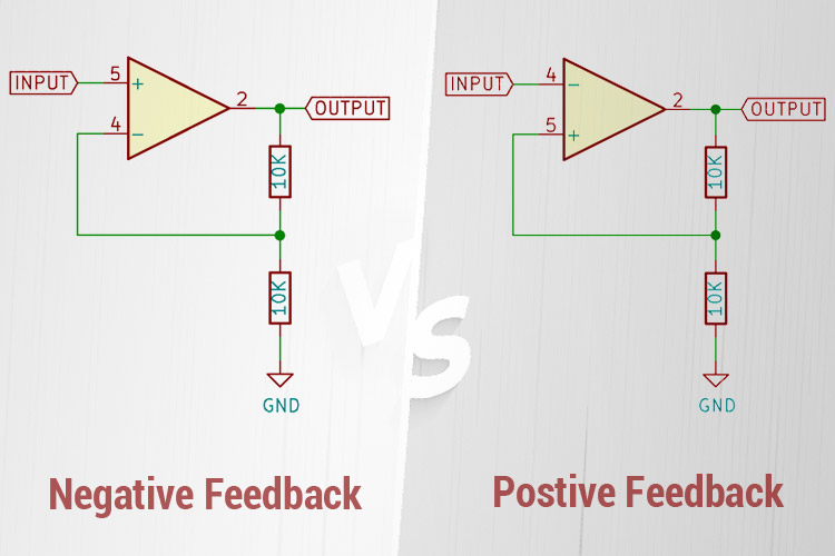
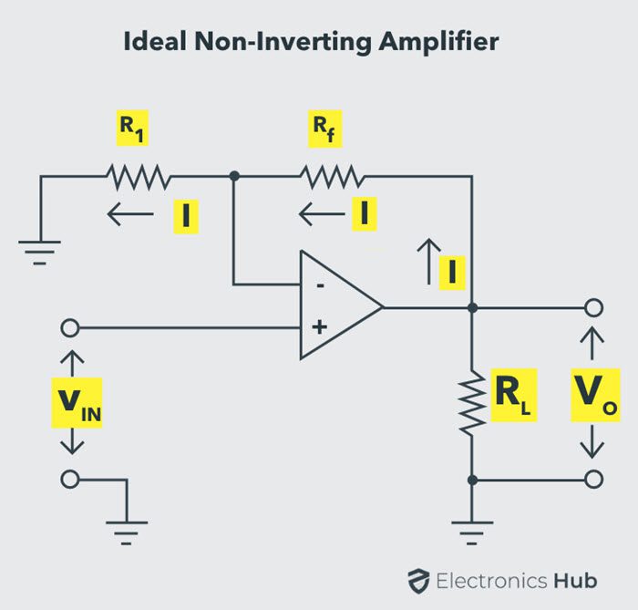
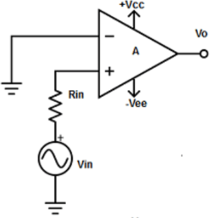
Select the correct circuit diagram of the basic inverting amplifier configuration.
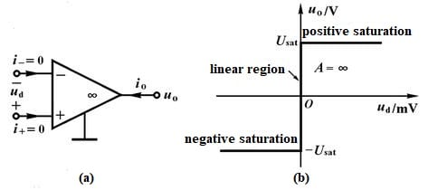
Operational Amplifier Basics - Op-amp tutorial Op-amp Parameter and Idealised Characteristic. Open Loop Gain, (Avo) Infinite - The main function of an operational amplifier is to amplify the input signal and the more open loop gain it has the better. Open-loop gain is the gain of the op-amp without positive or negative feedback and for such an amplifier the gain will be infinite but typical real values range from about 20,000 to 200,000. MOSFET Amplifier Circuit using an Enhancement MOSFET An common source mosfet amplifier is to be constructed using a n-channel eMOSFET which has a conduction parameter of 50mA/V 2 and a threshold voltage of 2.0 volts. If the supply voltage is +15 volts and the load resistor is 470 Ohms, calculate the values of the resistors required to bias the MOSFET amplifier at 1/3(V DD). Draw the circuit diagram. Microelectronic Circuits by Sedra Smith,5th ... - Academia.edu Microelectronic Circuits by Sedra Smith,5th edition
Select the correct circuit diagram of the basic inverting amplifier configuration.. Op Amp Differential Amplifier Circuit | Voltage Subtractor A Differential Amplifier, also known as Difference Amplifier, is a very useful op-amp configuration that amplifies the difference between the input voltages applied. A differential amplifier is a combination of both inverting and non-inverting amplifiers. It uses a negative feedback connection to control the differential voltage gain. Correct Circuit Diagram - U Wiring Oct 03, 2021 · Part A Select the correct circuit diagram of the basic inverting amplifier configuration ANSWER lin vo R R2 lin R2 R2 Ri in to R. For example two circuit breakers or fuses are used in electric range circuits. The kitchen electric range may also be found to have a 3-wire or 4-wire cord or 220 volt outlet which will require proper electrical ... 25 results in SearchWorks catalog Select search scope, currently: catalog all catalog, articles, website, & more in one search; catalog books, media & more in the Stanford Libraries' collections books, media & more in the Stanford Libraries' collections Solved Consider the circuit of the basic non-inverting - Chegg Question: Consider the circuit of the basic non-inverting amplifier configuration shown in figure below. Give an expression for the closed-loop voltage gain ...
Phase Shift Oscillators - Tutorialspoint The following circuit diagram shows a single section of an RC network. The output voltage V 1 ' across the resistor R leads the input voltage applied input V 1 by some phase angle ɸ o . If R were reduced to zero, V 1 ' will lead the V 1 by 90 o i.e., ɸ o = 90 o . Common Emitter Amplifier : Circuit Diagram, Working & Its ... The coupling capacitor C2 couples one stage of amplification to the next stage. This technique used to isolate the DC bias settings of the two coupled circuits. CE Amplifier Circuit Currents. Base current iB = IB +ib where, IB = DC base current when no signal is applied. ib = AC base when AC signal is applied and iB = total base current. Power Calculator Amplifier Audio Supply [G23ORI] Audio amplifier design tool This is a modelling tool for A/B class audio stereo amplifier power calculation For powering sensitive electronics, please use our MP-3242 Many computer builders select a power supply unit that is over-dimensioned for the computer system that they are building 4, 1994, addressed several of the PAS problems K5. Transistor Common Emitter Amplifier - Electronics Notes The circuit shown above is that if a basic AC coupled common emitter amplifier. The common emitter circuit can be used in a variety of forms. - sometimes as a transistor logic output, a directly coupled amplifier and in many areas. It is widely used, providing a good compromise between voltage and current gain along with input and output impedance.
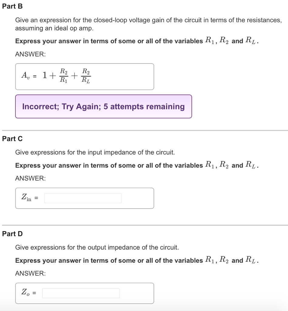
Best 3 MPPT Solar Charge Controller Circuits for Efficient ... 29/04/2020 · I want to design the same circuit for our mobile battery Having rating 2900 mAH/11.02Wh nominal charge voltage 3.8 V.Limited charge voltage 4.35 V as per any anroid mobile battery.Can I make the charger portable using the same pic based mppt technique or I should go for Linear technology or any other method mppt method to make the circuit portable. Solved Consider the circuit diagram of the basic inverting Consider the circuit diagram of the basic inverting amplifier configuration shown in the figure below. (Figure 1) Part A. Give an expression for the closed-loop voltage gain of the circuit in terms of the resistances, assuming an ideal op amp. Express your answer in terms of the variables R1 and R2. Part B Operational Amplifier Differentiator Circuit » Electronics ... Op amp differentiator circuit. It can be seen that the op amp circuit for an integrator is very similar to that of the differentiator. The difference is that the positions of the capacitor and inductor are changed. In its basic form the centre of the circuit is based around the operational amplifier itself. Feedback Amplifier : Types, Topologies, and Characterstics The block diagram of the current series feedback-amplifier is shown below, by which it is apparent that the feedback circuit is located in series by means of the output as well as the input. When the feedback circuit is allied in series through the o/p as well as the input, then both the o/p impedance & the i/p impedance will be increased.
Inverting Operational Amplifier (Op-amp): Circuit Design ... Jul 31, 2018 · Inverting Op-amp is called Inverting because the op-amp changes the phase angle of the output signal exactly 180 degrees out of phase with respect to input signal. Same as like before, we use two external resistors to create feedback circuit and make a closed loop circuit across the amplifier.
PDF Chapter 13: Basic Op-Amp Circuits - An-Najah National ... The summing amplifier is an application of the inverting op-amp covered in Chapter 12. The averaging amplifier and the scaling amplifier are variations of the basic summing amplifier. Summing Amplifier with Unity Gain A summing amplifierhas two or more inputs; normally all inputs have unity gain.
View and Set Configuration Bits - Developer Help Configuration Bits Configuration bits are a collection of specialized bits that can only be modified at program time. Configuration bits are "read" during reset and enable or disable hardware features in the microcontroller. The features controlled by the configuration bits include, but are not limited to, the clock source, Watchdog Timer ...
Solved Part A Select the correct circuit diagram of the - Chegg Part A Select the correct circuit diagram of the basic noninverting amplifier configuration. 2 3 4 Risu w Question: Part A Select the correct circuit diagram of the basic noninverting amplifier configuration. 2 3 4 Risu w This problem has been solved! See the answer See the answer See the answer done loading. if each box weights.
Inverting & Non-Inverting Amplifiers - D&E Notes A inverting amplifier provides the same function as the common emitter and common-source amplifiers. The schematic diagram for an inverting amplifier is shown in Figure (a). Observe that the offset and D.C. voltages have been left off of these circuits for simplicity. These connections are generally the same for all circuits using the same type of OP-AMP. The input signal is applied to the inverting (minus) input.
MPLAB® X IDE - Developer Help MPLAB ® X Integrated Development Environment (IDE) is a software program that runs on a PC (Windows ®, Mac OS ®, Linux ®) to develop applications for Microchip PIC ® microcontrollers and dsPIC ® digital signal controllers.. MPLAB X IDE provides an extensive array of features for developing and debugging applications on any device from the PIC microcontroller product …
Solved Draw the circuit diagram of the basic inverting - Chegg Draw the circuit diagram of the basic inverting amplifier configuration. Give an expression for the closed-loop voltage gain of the circuit in terms of the ...
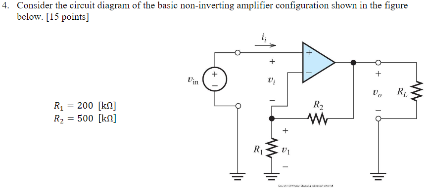
Solved 4. Consider the circuit diagram of the basic | Chegg.com Question: 4. Consider the circuit diagram of the basic non-inverting amplifier configuration shown in the figure below. [15 points] + + + + Vin V; V. R R2 R1 = ...
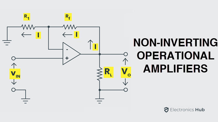
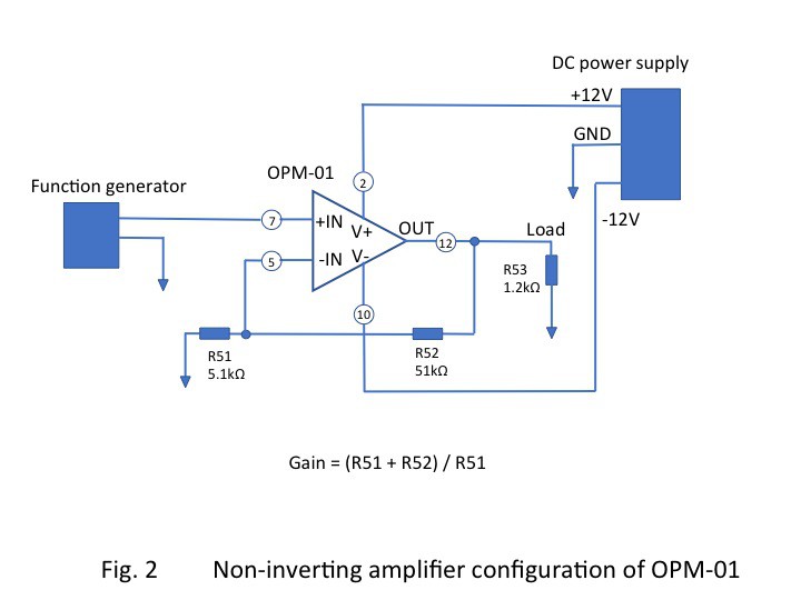
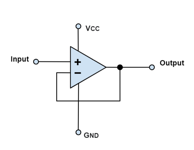
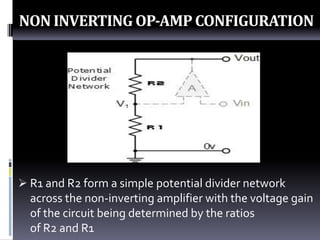
Non-Inverting Operational Amplifier Circuit » Electronics ... The non-inverting amplifier configuration is one of the most popular and widely used forms of operational amplifier circuit and it is used in many electronic devices. The op amp non-inverting amplifier circuit provides a high input impedance along with all the advantages gained from using an operational amplifier.
Op Amp Inverting Amplifier - Operational Amplifier Circuit ... The basic diagram for the inverting operational amplifier circuit is quite straightforward and only needs a few electronic components beyond the operational amplifier integrated circuit itself. Obviously the circuit is based around an operational amplifier, which is a differential amplifier with two inputs: inverting and non-inverting.
PDF Bipolar Transistor BJT - University of Pittsburgh configuration is an inverting amplifier circuit resulting in the output signal being 180o out-of-phase with the input voltage signal. The Common Collector (CC) Configuration . In the . Common Collector. or grounded collector configuration, the collector is now common through the supply. The
HamExam.org: Extra Question Pool Which of the following occurs when a satellite is using an inverting linear transponder? A. Doppler shift is reduced because the uplink and downlink shifts are in opposite directions; B. Signal position in the band is reversed; C. Upper sideband on the uplink becomes lower sideband on the downlink, and vice versa; D. All these choices are correct
Draw the circuit diagram of the basic inverting amplifier co ... Explanation. Step 1. 1 of 2. The circuit diagram of the basic inverting amplifier configuration is shown in figure below. Expression for the closed-loop voltage gain. A v A_v A v . if the circuit is: A v = v o v i n A_v=\frac {v_o} {v_ {in}} A v = v in v o . Input voltage.
Amplifier Supply Calculator Audio Power [NSGDHT] Search: Audio Amplifier Power Supply Calculator. About Power Audio Calculator Supply Amplifier
PDF Module 2 Unit 2 TRANSISTOR (BJT) Problems 2.1 A transistor has current gain of 0.99 when used in common base (CB) configuration. How much will be the current gain of this transistor in common emitter (CE) configuration ? Solution :- The current gain in common base circuit is written as α, and it has been given equal to 0.99.
Op-Amp IC's - Pin Configuration, Features ... - ElProCus Pin Configuration of 741 Op-amp Circuit Diagram 2. LM324. LM324 is a quad op amp integrated circuit with high stability, bandwidth which was designed to operate from a single power supply over a wide range of voltages. They have some dissimilar advantages over standard operational amplifier types in single supply applications.
Operational Amplifiers and Linear Integrated Circuits_Coughlin Operational Amplifiers and Linear Integrated Circuits_Coughlin. 558 Pages. Operational Amplifiers and Linear Integrated Circuits_Coughlin. Shomi Ahmed. Download Download PDF. Full PDF Package Download Full PDF Package. This Paper. A short summary of this paper. 36 Full PDFs related to this paper.
PDF Operational Amplifier Circuits - MIT OpenCourseWare Operational Amplifier Circuits as Computational Devices So far we have explored the use of op amps to multiply a signal by a constant. For the inverting amplifier the multiplication constant is the gain R2 − R1 and for the non inverting amplifier the multiplication constant is the gain R2 1+ R1. Op amps may also perform other
Simple Electronic Circuits for Beginners and Engineering ... Circuit Diagram. Simple Rain Water Alarm System. Circuit Operation. When there is no rain, the probes are not interconnected (here key button used in place of probes), and hence, there is no voltage supply to the inverting input of the OPAMP. As the non-inverting terminal is provided with a fixed voltage, the output of the OPAMP is at a logic ...
Solved 9. Consider the circuit diagram of the basic | Chegg.com Transcribed image text: 9. Consider the circuit diagram of the basic non-inverting amplifier configuration shown in the figure below.
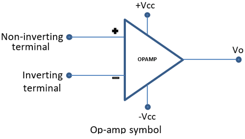
Basics Of Operational Amplifier - Tutorialspoint Basics Of Operational Amplifier. Operational Amplifier, also called as an Op-Amp, is an integrated circuit, which can be used to perform various linear, non-linear, and mathematical operations. An op-amp is a direct coupled high gain amplifier. You can operate op-amp both with AC and DC signals.
MCQs on OP AMP (Operational Amplifier) Questions and ... Right now, i am sharing the list of questions bank of the most basics and learning based MCQs on OP AMP (Operational Amplifier) questions and answers.If you have a little experience about the application of differential amplifier then you can easily understand the purpose of OP Amplifier.
(PDF) Microelectronic Circuits Sedra Smith 7th | Yasar ... Academia.edu is a platform for academics to share research papers.
Solved Part A Select the correct circuit diagram of the - Chegg Solved Part A Select the correct circuit diagram of the | Chegg.com. Engineering. Electrical Engineering. Electrical Engineering questions and answers. Part A Select the correct circuit diagram of the basic inverting amplifier configuration ANSWER lin vo R R2 lin R2 R2 Ri in to R.
Inverting Operational Amplifier - The Inverting Op-amp The Inverting Operational Amplifier configuration is one of the simplest and ... This effect produces a closed loop circuit to the amplifier resulting in ...
Gain-Bandwidth Product - an overview | ScienceDirect Topics The distortion of an amplifier is impacted by the open-loop distortion of the amplifier and the loop gain of the closed-loop circuit. The amount of open-loop distortion contributed by a CFB amplifier is small due to the basic symmetry of the internal topology. Speed is the other main contributor to distortion. In most configurations, a CFB amplifier has a greater bandwidth than …
Inverting Schmitt Trigger | Analog-integrated-circuits ... A part of output is fed back to the non-inverting (positive) input of the op-amp, hence called as positive feedback comparator. The inverting Schmitt trigger is shown below, The triggering point VT is calculated as VT=R2/(R1+R2 ) Vout. If Vout=+Vsat , VT=+ve If Vout=-Vsat , VT= -ve Thus when output is +Vsat, the upper threshold point is given as
Microelectronic Circuits by Sedra Smith,5th ... - Academia.edu Microelectronic Circuits by Sedra Smith,5th edition
MOSFET Amplifier Circuit using an Enhancement MOSFET An common source mosfet amplifier is to be constructed using a n-channel eMOSFET which has a conduction parameter of 50mA/V 2 and a threshold voltage of 2.0 volts. If the supply voltage is +15 volts and the load resistor is 470 Ohms, calculate the values of the resistors required to bias the MOSFET amplifier at 1/3(V DD). Draw the circuit diagram.
Operational Amplifier Basics - Op-amp tutorial Op-amp Parameter and Idealised Characteristic. Open Loop Gain, (Avo) Infinite - The main function of an operational amplifier is to amplify the input signal and the more open loop gain it has the better. Open-loop gain is the gain of the op-amp without positive or negative feedback and for such an amplifier the gain will be infinite but typical real values range from about 20,000 to 200,000.
![MCQ] Linear Integrated Circuit - Last Moment Tuitions](https://i.ibb.co/m46jFgz/9.png)











0 Response to "40 select the correct circuit diagram of the basic inverting amplifier configuration."
Post a Comment