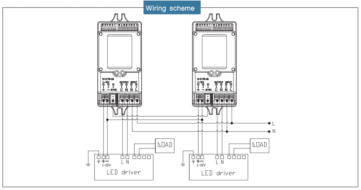
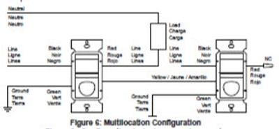
38 occupancy sensor wiring diagram
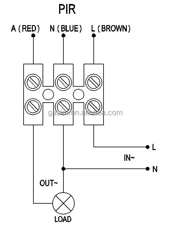
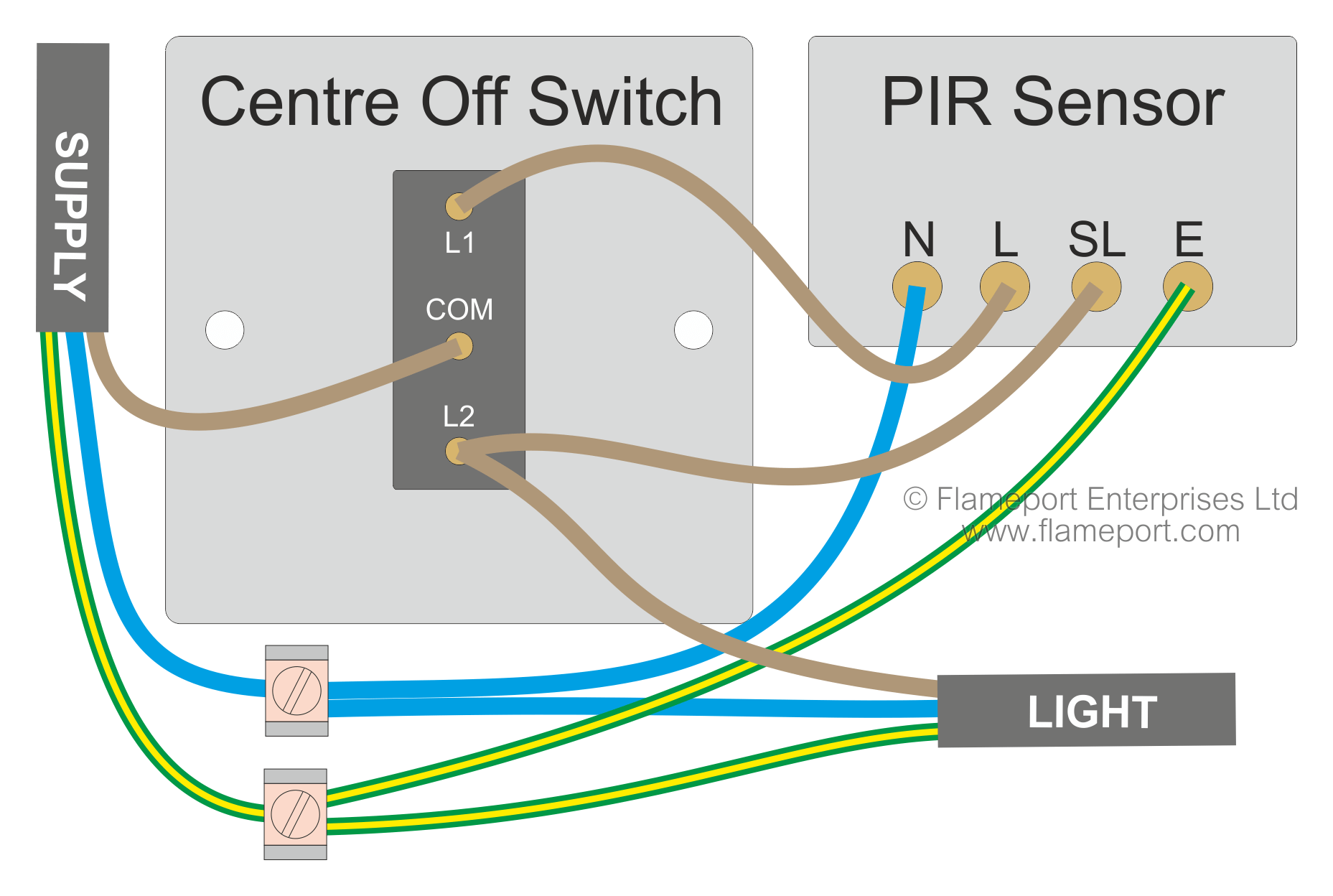
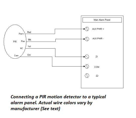
Low Voltage Occupancy Sensor Wiring Diagram Refer to the wiring diagram on the next page for the following procedures. Sfr 7 the sfr 7 series mini low bay sensor is a compact line voltage occupancy sensor that snaps directly into a small cavity in a fixture. When motion is detected the blue wire is electronically connected. Wiring a single lighting load controlled by occupancyconnect. PDF CONTROL - hubbellcdn These diagrams visually represent occupancy sensor design recommendations based on specific spaces in different building types 8 7 Restrooms are typically occupied less than 50% of the day, but lights are often left ON all the time. Significant savings can be achieved by using Hubbell Occupancy Sensors to automatically turn lights ON
Lutron Occupancy Sensor Switch Wiring Diagram - Wiring ... Lutron Occupancy Sensor Switch Wiring Diagram . October 9, 2020 1 Margaret Byrd . 0 . Occupancy sensor ods10 idw using sensing switch with lutron wired sensors pp multi location motion topgreener in wall pir maestro dual circuit box hard 048480 vacancy detectors. Occupancy Sensor Ods10 Idw ...
Occupancy sensor wiring diagram
PDF Multi-Technology Ceiling Mounted Occupancy Sensor • All sensors must be mounted at least 6 feet away from air vents. • Do not mount sensors closer than 10 feet from each other. • Do not touch the surface of the lens. Clean outer surface with a damp cloth only. Step 3 cont'd Mounting Option Diagram A Occupancy Sensor Mounted to Drop Ceiling Using Threaded Rod Low-Voltage Wires How To Install A 3-Way Motion Sensor Switch Installing a 3Way Occupancy Sensor. This is best accomplished by installing a 3-way Occupancy Sensor Switch. The switch should be available at your local hardware store. This switch should be installed in the main occupied or traffic location. As per the instructions, adjust the Duration of Time to remain On and Field of Vision and your set. Motion Detectors & Occupancy Sensors - Electrical 101 Occupancy Sensor Wiring Diagram 1 Occupancy sensor switch wires each have two black wires, (or one black and one red) and ground (green). One of the black line wires connects to line voltage from the panel, the other black (or red) load wire connects to the light (s). Each black wire can be a line or a load. Red is always the load wire.
Occupancy sensor wiring diagram. Leviton Occupancy Sensor Wiring Diagram - easywiring The wiring diagram is on the inside of the box. It really is intended to assist all of the common user in developing a correct program. Occupants must press the low voltage local switch to turn the load ON. Ceiling Occupancy Sensor Wiring Diagram Download - Motion Detector Wiring Diagram New Famous Leviton Pr180 Wiring. Occupancy Sensor Power Pack Wiring Diagram Sample occupancy sensor power pack wiring diagram - What's Wiring Diagram? A wiring diagram is a kind of schematic which uses abstract pictorial symbols to demonstrate all of the interconnections of components in a system. PDF Maestro Occupancy Sensing Switch Wiring Diagram 1 Occupancy sensing switch 120-277 V~White 50/60 Hz Ground Hot/Live Neutral Load Blue1 Bare Black Black Wiring Diagrams: 3-way Installation with Standard Mechanical Switch (120 V~)2, 4 -OPS6M2N-DV, -VPS6M2N-DV Black Blue White Ground Occupancy sensing switch Green Ground 120V~ 50/60 Hz Hot/Live Neutral Load Standard mechanical switch Occupancy Sensor Switch Wiring Diagram - Database - Wiring ... Occupancy Sensor Switch Wiring Diagram from img.favpng.com. Print the wiring diagram off plus use highlighters to trace the signal. When you make use of your finger or perhaps the actual circuit with your eyes, it is easy to mistrace the circuit. 1 trick that We 2 to printing a similar wiring plan off twice.
2 Pole Occupancy Switch Wiring - clipsal single pole ... 2 Pole Occupancy Switch Wiring - 17 images - leviton occupancy motion sensor ips06 hlw with wallplate, cooper gfci wiring diagram 4, double pole double throw switch rv photo gallery, single pole wiring diagram two switch complete wiring, How To Install Lutron 3 Way Occupancy Switch - U Wiring 50 Occupancy Sensors Lighting Wiring Diagram Af5u Security Lights Light Switch Wiring Motion Sensor . Let S Have A 3 Way Light Switch Wiring 3 Way Switch Wiring Dimmer Switch . Lutron Maestro Motion Sensor Switch With Wallplate 2 Amp Single Pole White Ms O2s Whw The Home Depot Light Sensor Switch Motion Sensor Lights Lutron . Hubbell Occupancy Sensor Wiring Diagram Wire the sensoras shown in the wiring diagram: The BL CK. The WSW is a passive infrared wall switch Occupancy Sensor combines PIR sensing technology, photocell control and Hubbell's patented three wire.mounting diagrams. SURFACE MOUNT SENSOR INSTALLATION 1. Turn power off at the service panel before installing sensor. 2. Leviton Occupancy Sensor Wiring Diagram - autocardesign Leviton Occupancy Sensor Wiring Diagram - wiring diagram is a simplified good enough pictorial representation of an electrical circuit. It shows the components of the circuit as simplified shapes, and the gift and signal contacts between the devices.
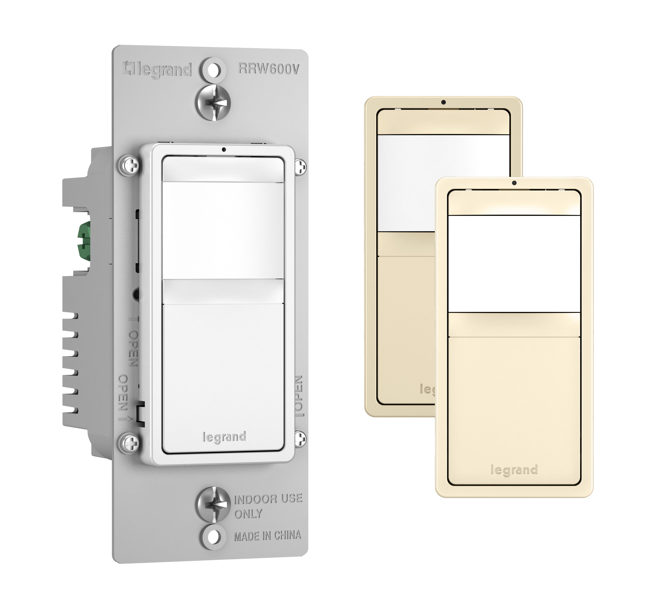
PDF Designer Wall Switch Occupancy Sensor - Leviton The Occupancy Sensor will turn the lights ON when motion is initially detected, and keep the lights ON for as long as motion is detected. ... Sensor Wiring Diagram 1: Single Control Application Wiring Diagram 2: Two Location Control Application NOTE: Either Sensor can turn the lights ON. Either Sensor must time-out to OFF, or both manual Occupancy Sensor Switch Wiring Diagram - easywiring Occupancy sensor wiring diagram 1. A wiring diagram is a streamlined conventional pictorial representation of an electric circuit. Valid wiring diagram for dimmer switch australia wiring diagram. Lutron occupancy sensor wiring diagram collections of patent us motion sensor switch for 3 way light circuit new. Each black wire can be a line or a load. PDF Multi-Technology Ceiling Mounted Occupancy Sensor Install back cover of the ceiling sensor to the wallboard or drop ceiling using the included screws, nuts and washers, or screws in combination with commercially available wall anchors. 5. Class II Wiring: Connect low-Voltage wires from Power Pack to Sensor per WIRING DIAGRAM as follows: Twist strands of each lead tightly and, with circuit Leviton Ceiling Occupancy Sensor Wiring Diagram Occupancy Sensor, Ceiling Mounted, Multi-technology, 24VDC, 30mA power exit), connect gray wire for photocell ambient light hold-off, degree harmonic .Leviton Occupancy Sensors Wiring Diagram Car Diagrams -> Source: schematron.org Ceiling mount wiring diagram occupancy sensors choosing the correct sequence of operation ceiling occupancy sensor ...
Hubbell Occupancy Sensor Wiring Diagram - Wiring World Hubbell occupancy sensor wiring diagram. Electrically connect the sensor to the lighting system per the applicable wiring. SURFACE MOUNT SENSOR INSTALLATION 1. Electrically connect the sensor to the lighting system per the applicable wiring diagram on page 2. Adjust sensor operation by setting DIP switches as described on page 2.
Motion Sensor Wiring Diagram - Wiring Diagram How To Wire Motion Sensor/ Occupancy Sensors - Motion Sensor Wiring Diagram You'll be able to usually count on Wiring Diagram being an crucial reference that will enable you to save time and cash. Using the help of this e-book, you are able to easily do your own personal wiring tasks.
Occupancy Sensors | Lighting Controls & Sensors | Lighting ... Instruction Sheets Specification Sheets Wiring Diagrams. Building Information Modeling (BIM) Files Customer Use Drawings. Company. About Press Releases Sales Agent Lookup . Where to Buy. Marketing. ... High Bay Occupancy Sensors and Controllers High Bay Occupancy Sensor. Compare. View Details.
Lutron Occupancy Sensor Switch Wiring Diagram Lutron Occupancy Sensor Switch Wiring Diagram - One of the most difficult automotive fix tasks that a mechanic or repair shop can agree to is the wiring, or rewiring of a car's electrical system.The trouble essentially is that every car is different. behind grating to remove, replace or repair the wiring in an automobile, having an accurate and detailed Lutron Occupancy Sensor Switch ...
PDF OCCUPANCY SENSOR - hubbellcdn OCCUPANCY SENSOR Installation Instructions SENSOR MODULE SPECIFICATIONS Timer Timeouts: ... Electrically connect the sensor to the lighting system per the applicable wiring diagram on page 2. 7. Adjust sensor operation by setting DIP switches as described on page 2. 8. Attach sensor lens to sensor module and rotate clockwise approximately five ...
PDF Vacancy Sensor Wiring Diagram Vacancy Sensor Wiring Diagram Common Source Manual ON Power 24V DC + Control ... Audible Alert 7 Visible Alert 8 Hold ON 9 ON OFF. MPC-50L Passive infrared Occupancy Sensü, *24VDC connect to MPP-24 or any other Class 2 Power Packs For Indoor use Only Revolution Lighting . Author: Joe Herbst Created Date:
PDF CI-24 Passive Infrared HVAC/BAS Ceiling Sensor The CI-24 occupancy sensor integrates with build-ing control systems via an internal isolated relay. The isolated relay has normally open and normally closed outputs and is rated for 1 Amp at 24 VAC/ VDC. The CI-24 connects to 24 VAC or 24 VDC building control systems. Power pack use is not necessary. When occupancy is detected, the sensor
Wiring Diagrams - lutron.com 3-Way Wiring with a Mechanical Switch (w/ Neutral) 3-Way Wiring with a Mechanical Switch (w/ Neutral) 120 V - 277 V: English (pdf) MS-VPS6M2U-DV: 3-Way Wiring with a Mechanical Switch (w/ Neutral) 3-Way Wiring with a Mechanical Switch (w/ Neutral) 120 V - 277 V: MS-OPS6M2N-DV: 4-Way Wiring with a Companion: 4-Way Wiring with a Companion ...
Motion Detectors & Occupancy Sensors - Electrical 101 Occupancy Sensor Wiring Diagram 1 Occupancy sensor switch wires each have two black wires, (or one black and one red) and ground (green). One of the black line wires connects to line voltage from the panel, the other black (or red) load wire connects to the light (s). Each black wire can be a line or a load. Red is always the load wire.
How To Install A 3-Way Motion Sensor Switch Installing a 3Way Occupancy Sensor. This is best accomplished by installing a 3-way Occupancy Sensor Switch. The switch should be available at your local hardware store. This switch should be installed in the main occupied or traffic location. As per the instructions, adjust the Duration of Time to remain On and Field of Vision and your set.
PDF Multi-Technology Ceiling Mounted Occupancy Sensor • All sensors must be mounted at least 6 feet away from air vents. • Do not mount sensors closer than 10 feet from each other. • Do not touch the surface of the lens. Clean outer surface with a damp cloth only. Step 3 cont'd Mounting Option Diagram A Occupancy Sensor Mounted to Drop Ceiling Using Threaded Rod Low-Voltage Wires

















0 Response to "38 occupancy sensor wiring diagram"
Post a Comment