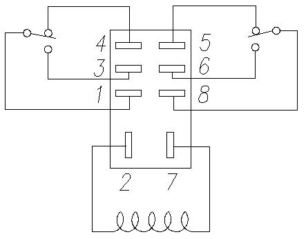
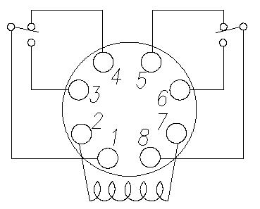
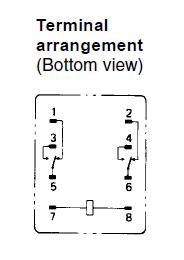
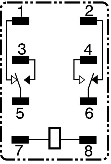
39 omron relay wiring diagram
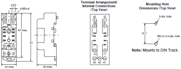
Omron Ly2 Relay Wiring Diagram Download - Wiring Diagram ... Apr 19, 2018 · Please download these omron ly2 relay wiring diagram by using the download button, or right visit selected image, then use Save Image menu. What is a Wiring Diagram? A wiring diagram is an easy visual representation in the physical connections and physical layout of the electrical system or circuit. OMRON Safety Relay G7SA Installation Guide - Manuals+ OMRON Safety Relay G7SA Installation Guide For pricing and availiablity in your local county please visit one of the below link Contents hide 1 Safety Relay 2 Specifications 3 Dimensions 3.1 G7SA-3A1B G7SA-2A2B 3.2 G7SA-5A1B G7SA-4A2B G7SA-3A3B 3.3 Track-mounting Socket P7SA-14F, P7SA-14F-ND 4 Precautions 5 Documents / Resources 5.1 Related Manuals / Resources Safety Relay … Continue reading ...
Omron H3ca A Wiring Diagram Download - Wiring Diagram Sample A wiring diagram is a simple visual representation of the physical connections and physical layout of the electrical system or circuit. It shows the way the electrical wires are interconnected and can also show where fixtures and components might be attached to the system. When and How to Use a Wiring Diagram
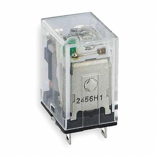
Omron relay wiring diagram
General-purpose Relays - Omron Europe Same mounting and internal wiring as the previous Super MK Relays. • Built-in mechanical indicator enables ... Operation checks in relay sequence circuits. 5 Pin Relay Wiring Diagram - Wiring Diagram 5 Pin Relay Wiring Diagram - Wiring Diagram is the graphical depiction of a complicated electrical circuit. It is extremely easy to attract a wiring diagram; you just need to have a great understanding on various types of wiring and also their objectives. Omron Relay Wiring Diagram - Wiring Diagram Line Wiring Diagram Relay Contactor Electrical Switches Electronics Burn Out Angle Png Pngegg New Original My4n Gs 220 240vac And 24vdc Omron Intermediate Relay 4no 4nc 14pin 3a Electricity 1no1nc Omron Plug In Relay Module Fy Ng2r
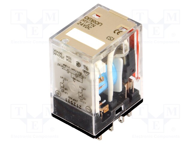
Omron relay wiring diagram. Omron My2n 24vdc Relay Wiring Diagram Many mature these ineffective wiring diagrams are offered free of charge, but the professional mechanic is best served to steer definite of them as they are generally not worth the paper they're printed on. Omron MY2N 24VDC (S), New, Japan, DPDT, Intermediate Relay 8 Pins, 10A/250VAC OMRON MY2N Relay Connection in Hindi (Practical) Omron Relay My4n Wiring Diagram - schematron.org Get The Best Ideas of Home Interior Design about omron relay wiring plc Wiring -Diagram Automotive Relay Wiring Diagram. Products 1 - 20 of Browse a wide range of Omron Relays. Free delivery on eligible orders. Order by 8pm for same day dispatch. Over products in. The MY4N DC 24 (S) is a miniature Power Relay with DC coil. Floatless Relay Diagram | Wiring | Omron 61F-G | Man Off ... Floatless Relay Wiring and diagram. Actual testing for its electrode and overall functions in tagalog language.#floatless#relay#omronThank you for watching g... Omron 24v Relay Wiring Diagram - IOT Wiring Diagram Omron General Purpose Relay 24v Dc Coil Volts 10a 120v Ac Contact Rating 2w930 Ly2 Dc24 Grainger. Dpdt relay omron my2n 240vac 24vdv my2 dc24 s automation and ly1n relays 50pcs ly2nj datasheet ly2n j 24vdc my2nj 24v power ขาย how to wire a d2 gs my4h us 11 pin spdt dc pinout of ly2 diy home 12dc 12v coil non circuit diagrams safety components 2nf 10a g7l 1a t 24dc images for free my4n ...
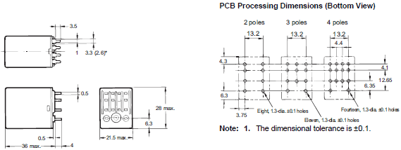
24v Relay Wiring Diagram 5 Pin - U Wiring The diagram above is the 5 pin relay wiring diagram. 12 24 Volt Dc 1500 Amp Series Parallel Solenoid Relay. 5 pin is compromised of 3 main pins and an SPDT single pole double throw. 24v flasher circuit diagram electronic unit 6 pin 3 1 flashers and hazards hazard 2 x 21w auto led electronics simplest lamp universal for turn. How To Wire A Relay The square relay pinout shows how the relay socket is configured for wiring. This pinout image is only a 2-pole diagram for room on the page purposes, but you can get the picture here with this one since a 3-pole will just have 1 more set of contacts. Miniature Power Relays - OMRON Industrial Automation Ask your OMRON representative for details on product specifications and the ability to manufacture products with voltages other than the above coil specifications. 3. The above models and specifications are new versions in the MY Series. 4. Except for MY2(N)-CR Relays with the above voltage specifications, all Relays have a height of 53 mm or less. How to Wire Up 8Pin relay to base - YouTube This tutorial will show you the basic operation and wiring to base for 8 pin 24Vdc and 240V AC relays
Timing Relay Wiring Diagram - Wiring Diagram and Schematic ... Wiring diagram relay omron h3cr a8 solid state timer time delay relays to cycle a traffic signal 326 327 series on super circuit with 555 electromechanical double best factory dc 12v 24v chint jss48a Gambar 3 Wiring Diagram Relay Omron H3cr A8 Scientific Solid State Timer Relay Electrical Academia Using Time Delay Relays […] 4 Prong Relay Wiring Diagram - Wirings Diagram 4 Prong Relay Wiring Diagram - 4 pin flasher relay wiring diagram, 4 pin relay wiring diagram 24v, 4 pin relay wiring diagram fan, Every electrical structure consists of various unique pieces. Each component ought to be set and connected with different parts in particular way. Otherwise, the structure won't function as it ought to be. Omron G3na 210b Wiring Diagram - namabayi.co Omron g3na 210b wiring diagram (NAMABAYI.CO) - The omron g3na solid state relay (ssr). 20 a at 200 to 480 vac. When an omron heat sink (refer to options (order separately)) or a heat sink of the specified size is used. • connect load following the wiring diagram in figure 2. 50 a at 200 to 480 vac. When ordering, specify the rated input voltage. Technical Guide for General-purpose Relays - Omron eData There are various magnetic circuits using non-polarized relays, but this section will describe the most common type, the hinged relay. The force to switch the ...
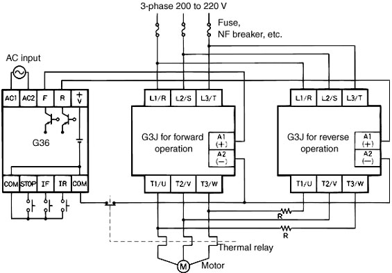
Smart Omron Safety Relay Wiring Diagram 3 Way Mini Toggle ... Omron safety relay wiring diagram. A wiring diagram is a simplified standard photographic depiction of an electrical circuit. A typical configuration for the operation control of machinery and equipment is shown in fig. Omron wiring diagram omron h3y 2 wiring diagram a control relay helps to prevent wires from overloading and overheating.
8 Pin Relay Wiring Diagram - Wiring Diagram 8 pin relay wiring diagram - You will want a comprehensive, professional, and easy to know Wiring Diagram. With such an illustrative guide, you'll be capable of troubleshoot, stop, and complete your tasks easily. Not merely will it help you attain your desired results quicker, but also make the complete procedure less difficult for everybody.
PDF Safety Relay Unit G9SA - Omron Safety Relay Unit G9SA • Four kinds of 45-mm wide Units are available: A 3-safety contact model, a 5-safety contact model, and models with 3 safe-ty contacts and 2 OFF-delay safety contacts. Also available are 17.5-mm wide Ex-pansion Units with 3 safety contacts and 3 OFF-delay safety contacts. • Two hand controller (type III C, EN 574)
220v 8 Pin Relay Wiring Diagram - Wiring Diagram Relay omron model my4n 3a 220v240 vac. If you need a relay diagram that is not included in the 76 relay wiring diagrams shown below please search our forums or post a request for a new relay diagram in our relay forum. Electro Mechanical Relay Beta Electric Industry Co Ltd Omron mk2p i ac 220v […]
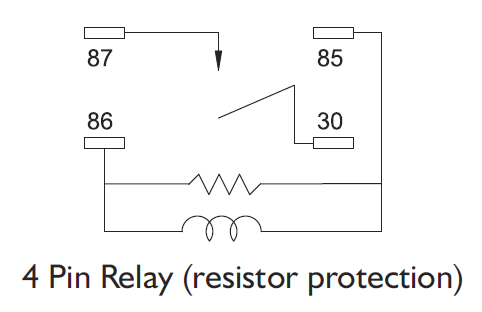
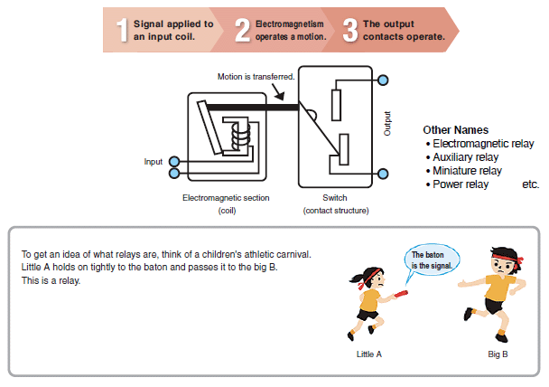
Omron 8 Pin Relay Wiring Diagram - Wiring Diagram 2 pole 8 pin relay pinout diagram. A relay consists of an electromagnet that receives an electric signal and converts it to a mechanical action and a switch that open and closes the electric circuit. Structure and principle of relays. 8 pin relay connection. The appropriate 8 pin socket are included with the plug in relay.
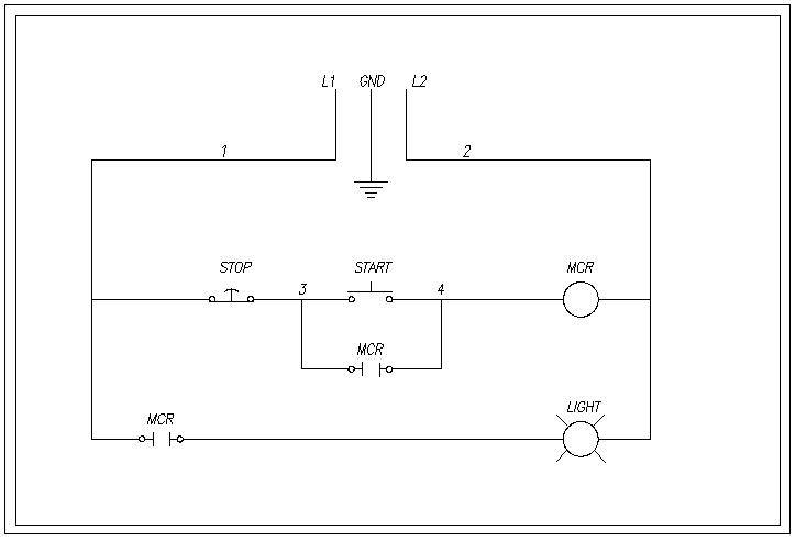
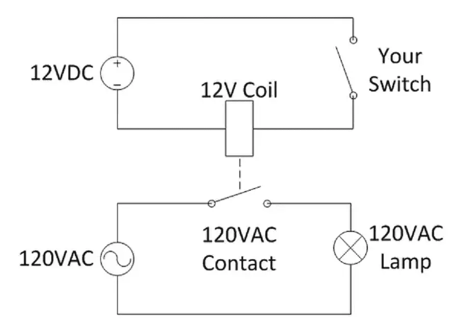
Overview of General Purpose Relays | OMRON Industrial ... 1. The input device (switch) is turned ON. 2. A current flows to the magnet (coil) to magnetize the core. 3. Magnetism causes the armature to be attracted to the core. 4. When the armature is attracted to the core, the moving contact touches the fixed contact and the lamp lights. Note: At this time, the release spring is stretched out. 5.
12 Volt Relays Wiring Diagram Omron Mks2pi Mechanical Indicator 12VDC. MKS2PIDC MKS2PI DC B. DPDT. 12 Volt Relay Wiring Diagram 12 volt relay wiring diagram scribd relay wiring diagram used for accessories in a 12volt system a relay is typically used to control a ponent that draws high amperage the relay relay diagrams quick reference the12volt how to wire relays and relay diagrams a quick reference of dozens of automotive relay ...
My2nj Relay Wiring Diagram - justussocializing.org 49 Wiring Diagram Plc Omron Pics The best another is always to use a verified and accurate My2nj Relay Wiring Diagram that's provided from a trusted source. A good, customary company that has a long track folder of providing the most up-to-date wiring diagrams easy to get to is not hard to find.
Omron H3cr Wiring Diagram Help - schematron.org Omron H3cr Wiring Diagram Help 12.01.2019 3 Comments schematron.org H3CR-F. DIN 48 × mm Twin Timers. • Wide power supply ranges of to VAC and 48 to . Electrical: , operations min. (5 A at VAC, resistive load at 1, operations/h) (See Block Diagrams. Socket (H3CR-A8E, to VAC, to VDC) ..
Omron Relay My4n Wiring Diagram This MY4-series relay has 4DPT Au-plated + Ag single contacts with built-in operation indicators. Omron Relay Wiring Diagram is one of the pictures we located on the internet omron relay my4n wiring diagram, omron relay wiring diagram. Except for MY2 (N)-CR Relays with the above voltage specifications, all Relays have a height of .. MY4N.
Omron Ly2 Relay Wiring Diagram - Free Wiring Diagram Nov 11, 2019 · Omron Ly2 Relay Wiring Diagram November 11, 2019 by Larry A. Wellborn Assortment of omron ly2 relay wiring diagram. A wiring diagram is a simplified standard photographic representation of an electrical circuit. It shows the components of the circuit as streamlined shapes, as well as the power and signal links between the devices.
Circuit Diagrams of Safety Components - Omron 1. List of Circuit Diagrams. This part presents basic examples in which a G9SA (Safety Relay Unit), G9SX (Flexible Safety Unit), F3SX (Safety Controller) and F3SP-B1P (Safety Light Curtain Controller) or D9M-CD1 (Safety Mat Controller) are used to configure an electrical interlock device connecting inputs and outputs. 2.
Omron Relay Wiring Diagram - Wiring Diagram Line Wiring Diagram Relay Contactor Electrical Switches Electronics Burn Out Angle Png Pngegg New Original My4n Gs 220 240vac And 24vdc Omron Intermediate Relay 4no 4nc 14pin 3a Electricity 1no1nc Omron Plug In Relay Module Fy Ng2r
5 Pin Relay Wiring Diagram - Wiring Diagram 5 Pin Relay Wiring Diagram - Wiring Diagram is the graphical depiction of a complicated electrical circuit. It is extremely easy to attract a wiring diagram; you just need to have a great understanding on various types of wiring and also their objectives.
General-purpose Relays - Omron Europe Same mounting and internal wiring as the previous Super MK Relays. • Built-in mechanical indicator enables ... Operation checks in relay sequence circuits.
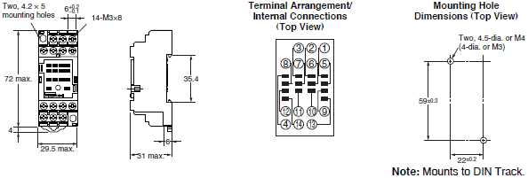


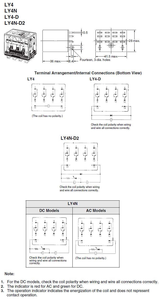

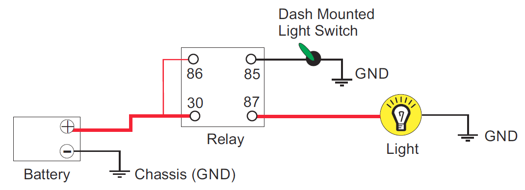







0 Response to "39 omron relay wiring diagram"
Post a Comment